- Introduction
- Short Answer
- Working Principle: Similar Discs Can Hide Different Processes
- Effective Area: Installed Surface Is Not Always Available Surface
- Available Head: A Small Loss Can Matter in a Gravity System
- Cleaning Is Part of the Process Design
- Engineering Practice: Specify Performance Before Choosing the Model
- Frequently Asked Questions (FAQ)
- Conclusion
- Sources
Introduction
An October 28, 2026 Water Magazine report highlighted INVENT’s sealed iFILT-S DYNAMIX disc filter for wastewater treatment. The engineering question behind this coverage is practical: how can a compact filter handle substantial flow when the available hydraulic head is limited? (watermagazine.co.uk)
The product should not be treated as an October launch. An INVENT-authored announcement published on April 8, 2026 already described the system, including its partially submerged stainless steel mesh wheels. The recent coverage brings renewed attention to that design; it does not establish newly demonstrated performance. (smartwatermagazine.com)
For beginning engineers, this provides a useful selection lesson. Maximum flow matters, but effective filtration area, solids loading, available head, cleaning demand, and maintenance access determine whether a filter will work in the actual plant.
Short Answer
Select a wastewater disc filter against a defined operating envelope, rather than a single catalogue flow rate.
Confirm:
- Required treated-water quality and representative feed conditions.
- Effective filtration area at actual operating levels.
- Hydraulic losses under clean and loaded conditions.
- Capacity during cleaning and equipment outages.
- Washwater supply, reject handling, and maintenance requirements.
A compact footprint is valuable only when the complete installation can reliably meet its treatment duty.
Working Principle: Similar Discs Can Hide Different Processes
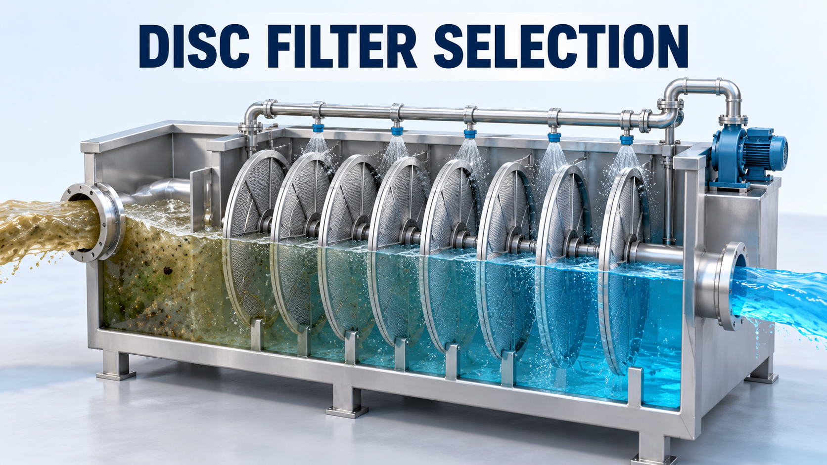
A disc filter provides a large filtration surface within a relatively small tank. Water passes through a filtering medium while suspended particles are retained. A cleaning system removes accumulated material.
However, “disc filter” describes an equipment arrangement, not one universal filtration mechanism.
INVENT describes the iFILT-S as an inside-out system: wastewater enters the rotor and passes through stainless steel mesh-covered wheels. Its announcement states that up to 60% of the filter surface can be submerged. These are manufacturer descriptions, not independent verification of performance on a particular wastewater. Source: INVENT, April 8, 2026.
By comparison, MITA’s technical overview describes pile-cloth systems in which water passes from outside the filter elements toward their interior. It distinguishes woven micro-screen media from three-dimensional free-fiber cloth. These different structures affect particle capture and cleaning behavior. The page does not display a publication date. (mitawatertechnologies.com)
Consequently, do not transfer a loading rate, cleaning assumption, or removal claim between products simply because both use discs.
Effective Area: Installed Surface Is Not Always Available Surface
A useful first calculation is hydraulic loading:
Hydraulic loading = flow rate ÷ effective filtration area
Consider an illustrative filter with 80 m² of installed media. Assume that only 40 m² is effectively available under the operating condition being checked.
At 400 m³/h:
400 ÷ 40 = 10 m³/(m²·h), equivalent to 10 m/h
Dividing by the full installed area would give 5 m/h and understate the loading on the available surface by half.
These numbers are an original teaching example, not sizing criteria for any commercial filter.
Ask the supplier how its quoted area is defined. Does it include both sides of each disc? How much remains submerged at minimum operating level? Is any area temporarily unavailable during cleaning?
Also separate hydraulic loading from solids loading. At the same flow, doubling the influent suspended-solids concentration doubles the incoming solids mass.
For example:
400 m³/h × 20 mg/L = 8 kg/h of incoming suspended solids
At 40 mg/L, the incoming load becomes 16 kg/h. Actual captured mass depends on removal efficiency.
The practical implication is that an upstream clarifier upset can challenge cleaning capacity even when flow remains unchanged.
Available Head: A Small Loss Can Matter in a Gravity System
Head expresses fluid energy per unit weight. KSB’s explanation of head distinguishes pump head from system head, while its pump-selection guidance accounts for losses in piping, valves, fittings, and entrances and exits. (ksb.com, ksbresourcecenter.com)
In a gravity-fed filter installation, the available water-level difference must accommodate the whole flow path.
Consider this illustrative head budget at the required flow:
Item
Assumed head
Available upstream-to-downstream head
0.60 m
Inlet piping and distribution losses
0.12 m
Outlet and downstream connection losses
0.10 m
Remaining allowance for the filter
0.38 m
If the filter requires 0.45 m under the loaded condition being evaluated, the installation cannot maintain that flow at the stated boundary levels.
A larger connection alone does not demonstrate that the problem is solved. The engineer should review pipe sizing, outlet submergence, operating levels, and the supplier’s hydraulic characteristics together.
Where pumping is necessary, assess the required duty across expected filter conditions. Increasing pump capacity without suitable level control can simply move the bottleneck upstream or cause overflow.
Cleaning Is Part of the Process Design
A filter that captures solids must also discharge them.
The Wisconsin DNR Advanced Wastewater Study Guide, February 2016, describes disc-filter arrangements and explains how solids accumulation can raise water levels and initiate cleaning. It also identifies poor backwashing and upstream treatment problems as factors affecting filtration operation. This is educational guidance, not a universal design standard. (dnr.wisconsin.gov)
Research also demonstrates why cleaning demand deserves attention. A 2003 study by Bourgeous and colleagues reported backwash consumption ranging from 2% to 10% of influent flow under the cloth-media filter conditions investigated. That result is specific to the tested system and conditions; it is not a design allowance for the INVENT unit. (pubmed.ncbi.nlm.nih.gov)
For a project, request both average cleaning consumption and instantaneous cleaning flow. The average affects the water balance; the instantaneous demand affects pump, pipe, and drainage sizing.
Review these equipment decisions:
- Washwater pump: Check required flow and pressure at the cleaning device after piping losses.
- Valves: Provide appropriate isolation and confirm that solids-bearing reject valves can handle the expected material.
- Reject piping: Check deposition risk, cleanout access, and destination capacity.
- Controls: Define responses to high upstream level, cleaning failure, and loss of washwater.
If cleaning reject returns upstream, include it in the receiving process balance.
Engineering Practice: Specify Performance Before Choosing the Model
Begin with the feed envelope: normal and peak flow, suspended solids, particle characteristics, temperature, and credible upset conditions.
Next, define what constitutes acceptable treatment. Turbidity and total suspended solids measure different properties; avoid assuming a fixed conversion between them.
Then establish a supplier review matrix:
Requirement
Evidence to request
Effluent quality
Applicable test or pilot data with feed conditions
Hydraulic capacity
Clean and loaded hydraulic characteristics
Effective area
Area definition and operating-level assumptions
Cleaning demand
Flow, pressure, frequency, and reject volume
Availability
Capacity during cleaning and planned maintenance
Materials
Suitability for wastewater and cleaning chemicals
These are recommended engineering checks, not quoted requirements from a particular code.
For unfamiliar industrial wastewater, representative testing can be more informative than increasing catalogue size. Oils, fibers, sticky solids, or fragile flocs may produce behavior that clean-water hydraulic data cannot predict.
Maintenance planning should include access to media, seals, drives, nozzles, instruments, and lifting points. Confirm how a unit is isolated and drained before deciding whether the installed arrangement provides sufficient availability.
Frequently Asked Questions (FAQ)
Does finer mesh always produce better overall treatment?
It may improve capture of some suspended particles, but can also change hydraulic resistance and cleaning demand. Select against the required effluent quality and actual feed.
Does a disc filter remove dissolved contaminants?
A suspended-solids filter does not establish removal of dissolved salts or organics. Different treatment mechanisms may be needed. The US EPA treatment overview identifies granular activated carbon as an adsorption medium and reverse osmosis as a treatment capable of removing various dissolved contaminants. These are distinct processes. (epa.gov)
Can rising head loss prove the filter is working correctly?
No. It can indicate solids accumulation, but should be assessed alongside flow, water levels, cleaning activity, and effluent quality.
Can continuous cleaning eliminate the need for spare capacity?
Continuous cleaning does not eliminate mechanical failure or maintenance outages. Required redundancy depends on the plant’s treatment obligations and available alternatives.
Conclusion
The recent disc-filter coverage highlights a useful design direction: fitting substantial filtration capacity into installations with limited space and available head.
The selection decision still depends on the complete system. Define effective area, evaluate solids loading, close the hydraulic budget, and design cleaning and reject handling alongside the filter. Those checks turn a promising equipment description into a reviewable engineering specification.
Sources
- Water Magazine — “INVENT introduces sealed version of iFILT DYNAMIX®-Disk Filter”. October 28, 2026. Recent trade coverage.
- INVENT — “A new benchmark in tertiary wastewater filtration”. April 8, 2026. Manufacturer-authored announcement hosted by Smart Water Magazine.
- MITA Water Technologies — Pile Cloth Filters for Wastewater Treatment: an Overview. Undated manufacturer technical explanation.
- Wisconsin DNR — Advanced Wastewater Study Guide. February 2016 edition, filtration sections.
- Bourgeous et al. — Performance evaluation of a cloth-media disk filter for wastewater reclamation. November–December 2003. Water Environment Research, 75(6), 532–538.
- KSB — Head and Selecting Centrifugal Pumps. Manufacturer engineering references; publication dates not confirmed.
- US EPA — Overview of Drinking Water Treatment Technologies. Government technical overview; publication date not confirmed.