- Introduction
- Short Answer
- Working Principle: Excitation, Response, and Fatigue
- Worked Example: A Variable-Speed Pump and a 24 Hz Pipe Mode
- Engineering Practice: Choose a Fix That Matches the Cause
- Commissioning and Maintenance: Measure at the Detail That Matters
- Frequently Asked Questions (FAQ)
- Conclusion
- Sources
Introduction
On November 2, 2026, the Society of Petroleum Engineers published an ADIPEC case study on vibration mitigation in acid gas recovery units. The author reported recurring failures at welded vessel support attachments connected to 36-inch solvent piping. A planned increase in throughput made the problem more urgent: the plant needed evidence that the piping could operate at higher rates without repeating the damage. (onepetro.org)
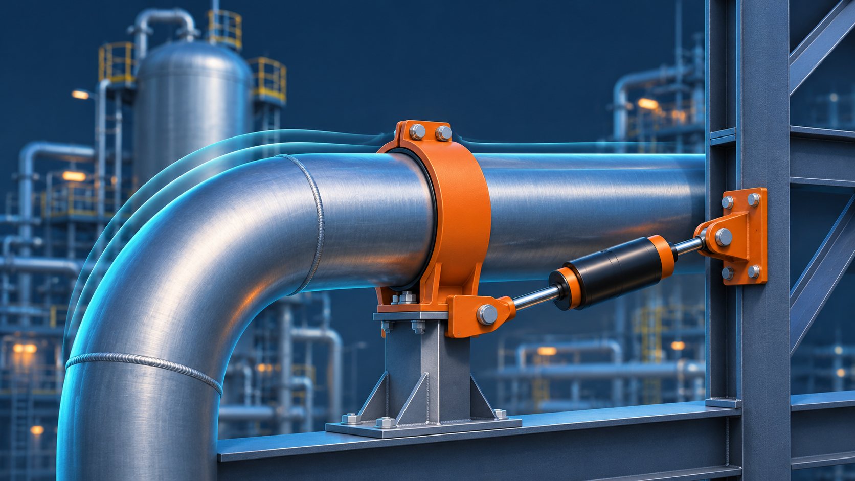
The published abstract describes a retrofit that combined changes to the support arrangement and load paths with viscous dampers and local piping modifications. The team used field vibration and strain measurements and checked the modified system at increased production rates. Because several changes were made together, the reported result does not isolate the effect of the dampers. It does show why a support modification should be evaluated against the operating conditions it is intended to handle. (onepetro.org)
Short Answer
Before stiffening a vibrating pipe, identify what is exciting it, how the pipe and its supports respond, and where cyclic stress is concentrated. A stiffer support can move one natural frequency away from a troublesome excitation. It can also bring another mode into play, restrict thermal growth, or transfer load into a weld or equipment nozzle.
For a retrofit, define the operating cases first. Then compare changes to the excitation source, support geometry, and damping. Verify the chosen modification at the locations that could fail and under the operating conditions that matter.
Working Principle: Excitation, Response, and Fatigue
Excitation is the force or motion that drives vibration. A pump can transmit periodic forces into its connected piping. A throttling valve can generate flow disturbances, and gas and liquid moving together can create fluctuating forces. The pipe, fluid, valves, and supports determine how strongly the system responds. Emerson’s control valve vibration guidance notes that vibration observed at a valve can also originate in the surrounding piping or equipment. (emerson.com)
When a periodic excitation is close to a natural frequency and acts in a direction that drives the corresponding mode, the response can increase sharply. Stiffness and mass influence the natural frequency; damping dissipates energy and can reduce the response near resonance. MIT OpenCourseWare’s lecture on driven oscillators explains these relationships using a simple oscillator. (ocw.mit.edu)
Fatigue depends on repeated local stress. The middle of a span may show the largest motion, while a support weld or branch connection experiences the most damaging cyclic stress. A motion reading is useful for screening, but it does not by itself establish the stress range or remaining life of a weld.
Worked Example: A Variable-Speed Pump and a 24 Hz Pipe Mode
Consider a hypothetical pump operating from 1,200 to 1,800 rpm. Suppose field measurements show a component at one cycle per shaft revolution, commonly called 1× running speed. A modal test identifies a nearby piping mode at 24 Hz. These are teaching assumptions, separate from the ADIPEC case.
The 1× excitation range is:
1,200 ÷ 60 to 1,800 ÷ 60 = 20 to 30 Hz
That excitation crosses 24 Hz at:
24 × 60 = 1,440 rpm
The next useful check is whether the pipe response actually peaks near 1,440 rpm and whether that mode loads the detail of concern. A frequency match alone does not identify the source or prove damaging stress.
Suppose a proposed brace moves that mode to 38 Hz, as predicted by a model. The modified mode is outside the 1× operating band. But if a meaningful 2× component exists, its normal operating band is 40 to 60 Hz. The machine would pass through the 2× crossing at 1,140 rpm during startup, assuming it ramps through that speed. The importance of that crossing depends on the force at 2×, the time spent there, and the measured response. The model should also be checked for changes in other modes.
This is why a design review needs the speed range, significant excitation frequencies, and startup behavior, even when the pump datasheet lists one rated speed.
Engineering Practice: Choose a Fix That Matches the Cause
Finding
Option to investigate
What to verify
A pressure-reducing valve generates significant excitation
Reassess valve sizing, trim, or pressure staging
Actual differential pressure and flow across the operating range, including low flow
A flexible span or heavy branch responds strongly
Change support location, shorten the unsupported span, or revise the branch layout
New frequencies, support reactions, thermal travel, and equipment nozzle loads
Response remains high near a mode that is difficult to avoid
Evaluate a damper
Direction of motion, relative movement across the damper, available stroke, and attachment loads
For a pump circuit, record speed, flow, suction and discharge conditions, and the active pump combination before attributing the vibration to resonance. A strong response at a particular speed may justify a frequency investigation; a response that changes with valve position at constant speed points to another useful test. In either case, check the source before buying a support component.
For a proposed damper, ask the supplier how force depends on motion and temperature, how much travel is available, and what inspection the device needs. Check the supporting steel as well as the pipe attachment: a damper needs relative movement across its two ends to dissipate energy. Verify that the installation also accommodates expected thermal movement.
Commissioning and Maintenance: Measure at the Detail That Matters
Start with a walkdown against the as-built piping arrangement. Record missing restraints, loose hardware, changed support gaps, and heavy valves or instruments on small branches. If a support weld has already failed, include the attachment and surrounding material in the integrity assessment. Repairing the visible damage alone leaves the original cyclic load path unexplained.
For a before-and-after comparison, record the measurement location, direction, quantity, and units, together with the operating state. Compare like with like. Where screening indicates that local cyclic stress could govern, a specialist may use strain measurements and a fatigue assessment. The Energy Institute’s process pipework guidance, second edition, January 2008, describes a staged approach to screening, assessment, and mitigation. (energyinst.org)
Record the operating range covered by the verification and the conditions that would trigger reassessment, such as a higher throughput, a changed pump speed range, or a heavier valve actuator. Confirm the piping code edition adopted by the project. ASME’s catalog lists B31.3-2024 for Process Piping; the applicable edition depends on the project and jurisdiction. (asme.org)
Frequently Asked Questions (FAQ)
Does a successful hydrostatic test rule out vibration fatigue?
No. A hydrostatic test does not reproduce the repeated loads generated by operating equipment or process flow.
Is the point with the largest visible movement where a crack will start?
Not necessarily. Check where the pipe bends and transfers load, particularly at welded attachments and small branches.
Can a damper replace a weight support?
Do not assume it can. Confirm which component carries the sustained weight and which controls dynamic movement. Verify both duties against the selected hardware and installation.
Conclusion
Treat a vibrating pipe as part of a system that includes its fluid, connected equipment, and supporting structure. Identify the excitation, check how the proposed fix changes the response and load path, and verify the result where cyclic stress matters. That evidence is more useful than a quieter pipe at a single operating point.
Sources
- Al Jaberi, A. S. — Restoring Mechanical Integrity and Enabling Capacity Growth Through Advanced Vibration Mitigation of AGRU Piping Systems. SPE-235252-MS, published November 2, 2026. Case details are drawn from the published abstract.
- Energy Institute — Guidelines for the Avoidance of Vibration Induced Fatigue Failure in Process Pipework. Second edition, January 2008. The publisher also lists an erratum.
- MIT OpenCourseWare — Driven Oscillators, Transient Phenomena, Resonance. Course materials, Fall 2016.
- Emerson — Control Valve Vibration. Manufacturer technical guidance; publication date not stated.
- ASME — B31.3 Process Piping. 2024 edition. Project or jurisdictional adoption dates should be verified separately.