- Introduction
- Short Answer
- Working Principle: Two Drive Systems, One Transfer Duty
- Worked Example: Establish the Useful Hydraulic Power
- Estimate the Pneumatic Pump’s Electrical Burden
- Why Avoided Air Demand Is Not Automatically Avoided Electricity
- Compare Energy per Completed Transfer
- Check the Hydraulic System Before Selecting the Replacement
- Maintenance and Commissioning: Keep the Comparison Repeatable
- Frequently Asked Questions (FAQ)
- Conclusion
- Sources
Introduction
On November 5, 2026, Graco announced the global launch of its QUANTM i230 electric double-diaphragm pump, targeting high-flow applications traditionally served by pneumatic pumps. The manufacturer identifies paint, coatings, and ceramics production among its applications and claims energy reductions of up to 80% compared with pneumatic pumps. That percentage is a manufacturer claim, not a guaranteed saving for every installation. This article draws from the past seven days of announcements. (investors.graco.com)
The engineering question behind the announcement is practical: if a pump stops consuming compressed air, how much electricity will the factory actually save?
An air-operated pump may have no electrical cable, but its energy comes from an electrically driven compressor elsewhere in the plant. Comparing it with an electric pump therefore requires a boundary that includes the compressed-air system.
Short Answer
Compare the electricity required to complete the same transfer duty, including the effect on the air compressor.
For the pneumatic option, determine air consumption at the required liquid flow and pressure. Then estimate—and later verify—how the compressor responds when that demand disappears.
For the electric option, include the drive, controls, and relevant auxiliaries.
Use kWh per completed batch or kWh per cubic metre transferred alongside transfer time. A lower pump energy requirement becomes a site electricity saving only when the compressed-air system reduces its electrical consumption accordingly.
Working Principle: Two Drive Systems, One Transfer Duty
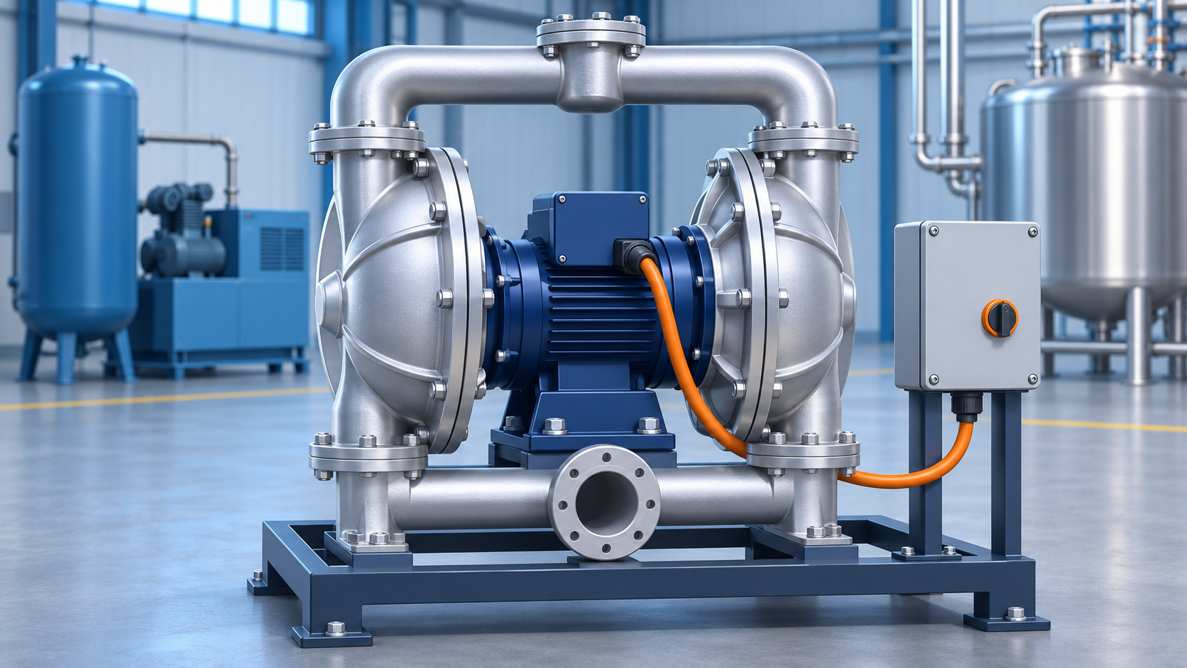
A double-diaphragm pump uses reciprocating diaphragms and check valves to draw liquid into pumping chambers and discharge it into a common outlet.
An air-operated double-diaphragm pump uses compressed air to drive that motion. An electric version supplies mechanical work through an electric drive.
Both must overcome the same process requirements: elevation, vessel pressure difference, and resistance in piping, hoses, valves, and equipment. Changing the drive does not remove those requirements.
Graco’s i230 product description describes integrated speed control and diaphragm-pump capabilities such as self-priming and stalling under pressure within approved operating limits. Those capabilities should be checked for the selected configuration rather than assumed for every electric positive-displacement pump. (graco.com)
Worked Example: Establish the Useful Hydraulic Power
Consider a hypothetical liquid-transfer duty:
Input
Assumed value
Liquid flow
300 L/min
Differential pressure across the pump
3.0 bar
Electric package input at that duty
3.0 kW
Annual operation at that duty
4,000 hours
These values are teaching assumptions, not i230 performance data.
For an approximately incompressible liquid:
Hydraulic power = volume flow × differential pressure
Convert the units:
300 L/min = 0.005 m³/s
3.0 bar = 300,000 Pa
Therefore:
Hydraulic power = 0.005 × 300,000 = 1,500 W = 1.5 kW
With the assumed 3.0 kW package input:
Package efficiency at this point = 1.5 ÷ 3.0 = 50%
The hydraulic calculation is a useful consistency check. It does not predict input power by itself. Obtain the supplier’s performance data for the actual fluid, operating point, and selected pump materials.
Also use the pressure rise across the pump, not simply a discharge gauge reading, when calculating hydraulic power.
Estimate the Pneumatic Pump’s Electrical Burden
Suppose the existing pneumatic pump consumes 2.0 m³/min of air, expressed on an explicitly defined free-air reference basis.
Assume the plant currently assigns 7.0 kW per m³/min of delivered free air to this service. The flow reference basis must match between the air measurement and the power factor.
The allocated electrical burden is:
2.0 × 7.0 = 14.0 kW
Compared with the assumed electric package:
Estimated power reduction = 14.0 − 3.0 = 11.0 kW
At 4,000 operating hours:
Estimated annual energy reduction = 11.0 × 4,000 = 44,000 kWh
The corresponding reduction is approximately 79%.
This result comes entirely from the stated assumptions. Its similarity to a promotional percentage does not validate that percentage or predict a particular product’s performance.
More importantly, the calculation allocates compressor energy to the pump. It does not yet prove that removing the pump will reduce compressor power by 14 kW.
Why Avoided Air Demand Is Not Automatically Avoided Electricity
Compressors respond differently to reduced demand.
The U.S. Department of Energy’s compressed-air sourcebook explains that part-load performance depends strongly on compressor type and controls. An unloaded compressor can continue consuming electricity even while delivering no useful air. (energy.gov)
For a replacement project, the important quantity is therefore the change in compressor-system electrical input under comparable production conditions.
Suppose measurements show:
Measurement
Average power
Compressor system before replacement
85 kW
Compressor system after replacement
75 kW
New electric pump package
3 kW
Assume the comparison covers matched operating conditions, other air demands are unchanged, and the pump operates throughout the measured periods.
Then:
Net site power reduction = 85 − 75 − 3 = 7 kW
Applied to the assumed 4,000 annual operating hours:
Annual energy reduction = 7 × 4,000 = 28,000 kWh
That is lower than the initial 44,000 kWh estimate.
The new pump can still be beneficial. The difference shows why an average compressed-air energy allocation and the actual electricity avoided by a project are different quantities.
In practice, measure over enough time to capture compressor cycling and production variation. A brief reading taken during a load/unload transition is weak evidence.
Compare Energy per Completed Transfer
Power alone can mislead when transfer times differ.
Assume a 9 m³ batch is transferred at 300 L/min:
Transfer time = 9,000 ÷ 300 = 30 minutes
At the assumed electric input:
Batch energy = 3.0 kW × 0.5 h = 1.5 kWh
Therefore:
Specific transfer energy = 1.5 ÷ 9 ≈ 0.167 kWh/m³
For a fair comparison, transfer the same liquid volume between the same starting and finishing conditions. Include priming, recirculation, waiting, and cleaning where they form part of the relevant operating cycle.
A faster pump may use more instantaneous power yet less energy per batch. Conversely, reducing speed may save little if it substantially extends operating time.
Check the Hydraulic System Before Selecting the Replacement
Establish the required flow at the actual differential pressure. Do not assume that a published maximum flow and maximum pressure occur together.
Review the following application details:
Item
Selection question
Suction arrangement
Can the pump fill reliably at the lowest source level and highest expected viscosity?
Discharge network
What pressure is required with the actual hoses, valves, filters, and destination conditions?
Fluid properties
How do temperature, solids, and viscosity change during production and cleaning?
Wetted materials
Are diaphragms, balls, seats, seals, and the pump body compatible?
Pressure protection
What happens if a discharge valve closes or the control system fails?
Electrical installation
Is the selected model suitable for the location, supply, and area classification?
Graco lists configuration-specific materials and electrical requirements in its individual product information. Confirm the exact model and approvals before treating an electric pump as a direct replacement. (graco.com)
Maintenance and Commissioning: Keep the Comparison Repeatable
Record a baseline before removing the pneumatic pump: liquid volume, transfer time, suction and discharge pressures, air consumption, and representative fluid conditions.
After replacement, repeat the transfer and measure package electrical energy. Check whether pulsation affects instruments, hoses, or downstream equipment. Verify alarms, remote controls, and the approved response to blocked discharge.
Include maintenance in the economic comparison. Electric drive removes the pump’s operating-air demand, but diaphragms, check valves, and other fluid-contact parts still require inspection and service.
Keep energy savings, maintenance changes, and additional production capacity as separate benefits so they can each be supported by evidence.
Frequently Asked Questions (FAQ)
Does removing one pneumatic pump allow a compressor to stop?
Possibly, but it depends on the remaining demand, compressor sequencing, storage, and operating limits. Verify the system response.
Can compressor nameplate power be used to calculate the saving?
Not alone. Nameplate information does not establish actual power at the plant’s operating conditions or the reduction after demand changes.
Is an electric diaphragm pump always the best choice?
No. Compare fluid suitability, duty cycle, installation requirements, maintainability, and measured energy performance for the application.
Conclusion
Evaluate diaphragm-pump electrification through a matched transfer duty and a plant-level energy balance.
Calculate hydraulic power, measure the new package’s input, and verify the compressor electricity actually avoided. Reporting energy per completed transfer turns an efficiency claim into a result that engineers can review and operators can reproduce.
Sources
- Graco — QUANTM i230 Launch Announcement. November 5, 2026, 4:16 p.m. EST. Manufacturer announcement; energy reduction is a manufacturer claim.
- Graco — QUANTM i230 Product Group. Manufacturer product information; publication date not stated.
- Graco — TE230-0005 Configuration. Configuration-specific product information; publication date not stated.
- U.S. Department of Energy and Compressed Air Challenge — Improving Compressed Air System Performance. Third edition, publication DOE/EE-1340; particularly Fact Sheet 5 on compressor controls. Publication date not verified from the document.
Sources checked November 8, 2026. Numerical examples are illustrative. This article does not assert a new standard requirement or a product-specific energy guarantee.