- Introduction
- Short Answer
- Working Principle: Heat Output Comes from Two Inputs
- Worked Example: A 1 MW Heating Duty at COP 5
- What Happens When Only 600 kW of Source Heat Is Available?
- Available Heat Must Also Be Recoverable Heat
- COP Changes When the Measurement Boundary Changes
- Translate the Heat Balance into Piping Requirements
- Match Source Availability to Heating Demand
- Commissioning and Maintenance: Verify Useful Heat
- Frequently Asked Questions (FAQ)
- Conclusion
- Sources
Introduction
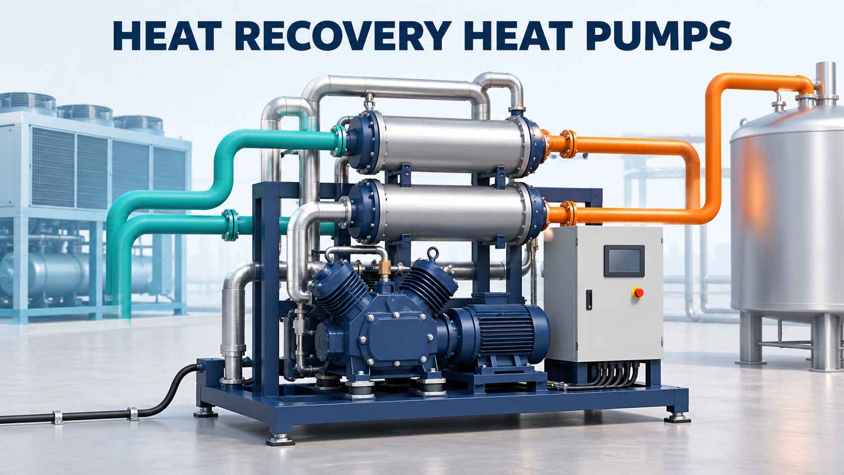
Johnson Controls’ announcement dated November 2, 2026 introduced the FRICK HeatPAC Reciprocating Ammonia Heat Pump for food and beverage facilities. The system recovers heat from ammonia refrigeration and supplies higher-temperature hot water. Although the page URL contains an October date, the release body explicitly states November 2. (johnsoncontrols.com)
The manufacturer’s efficiency comparison with gas boilers is based on internal modeling. It should not be treated as measured performance at every installation—or automatically translated into a particular coefficient of performance.
The practical question is broader: how much recoverable heat is available when the plant needs hot water, and what electrical loads belong in the comparison?
This article develops those checks through a simple energy balance. Its focus is source availability and system performance, extending the heat-exchanger selection topic into plant integration.
Short Answer
Define three quantities before selecting a heat recovery heat pump:
- Required useful heating output
- Available source heat at suitable conditions
- Electrical input within a clearly stated boundary
Then check their variation over time.
A high COP does not establish that sufficient waste heat is available, that the required temperature can be achieved, or that the complete installation will deliver the same efficiency as the packaged machine.
Working Principle: Heat Output Comes from Two Inputs
A compression heat pump absorbs heat at a lower temperature and transfers it to a higher-temperature destination using mechanical work.
New Zealand’s Energy Efficiency and Conservation Authority describes the refrigerant cycle: heat absorption, compression, and heat delivery through an exchanger. (eeca.govt.nz)
For an idealized steady-state balance with negligible external losses:
Useful heating output = absorbed source heat + work input
This explains why heating output can exceed electrical input. The additional energy is transferred from the source; it is not created.
The IEA’s explanation in The Future of Heat Pumps, published in 2022, likewise distinguishes transferred heat from the energy needed to operate the machine. (iea.org)
For real equipment, use the supplier’s performance data and stated energy boundary, including the treatment of motor losses and auxiliaries.
Worked Example: A 1 MW Heating Duty at COP 5
Consider a hypothetical heat pump with:
Input
Assumed value
Useful heating output
1,000 kW
Heating COP
5.0
External heat losses
Neglected
For this simplified example, treat electrical input as work entering the thermodynamic balance.
Heating COP is:
COP = useful heating output ÷ input power
Therefore:
Input power = 1,000 ÷ 5 = 200 kW
The required source heat is:
1,000 − 200 = 800 kW
The balance is:
Contribution
Power
Heat absorbed from the source
800 kW
Work input
200 kW
Heating output
1,000 kW
These are original teaching assumptions, not FRICK HeatPAC performance data.
The important selection result is that a 1 MW heating requirement does not imply a 1 MW waste-heat requirement. Under the assumed conditions, it requires 800 kW of source heat plus 200 kW of work.
Equally, a compressor rated for the electrical input cannot deliver that heating output without the necessary source conditions.
What Happens When Only 600 kW of Source Heat Is Available?
Suppose the recoverable source heat falls to 600 kW.
For illustration only, assume COP remains 5:
Heating output = 5 × work input
Combining this with the energy balance:
600 + work input = 5 × work input
Therefore:
Work input = 600 ÷ 4 = 150 kW
Heating output = 750 kW
The assumed 1 MW heating requirement now has a 250 kW shortfall.
This calculation illustrates source limitation. It is not a prediction of how a real machine will unload.
Actual COP, compressor capacity, operating limits, and control behavior change with conditions. Obtain a supplier performance map covering the expected source and hot-water temperatures and flows.
Also establish what happens to the process during a shortfall: slower heating, thermal storage discharge, supplementary heating, or another approved response.
Available Heat Must Also Be Recoverable Heat
A refrigeration plant’s total heat rejection is not automatically the heat available to a proposed recovery connection.
Identify:
- Where heat will be extracted
- Its temperature and pressure conditions
- The permitted effect on refrigeration operation
- The recoverable duty across operating cases
- Fouling or contamination constraints
- Whether an intermediate circuit is required
A source may contain substantial energy at a temperature or location that does not suit the selected equipment.
The Australian Government’s waste-heat recovery guidance identifies refrigeration as a potential source and emphasizes suitable design and implementation. It also describes different recovery arrangements, rather than one universal connection method. (energy.gov.au)
Prepare the recovery interface with the refrigeration-system designer. A hot-water project should not undermine the process cooling duty it depends on.
COP Changes When the Measurement Boundary Changes
ASHRAE’s heat recovery guidance distinguishes heat-pump COP from system COP, which includes the energy input of the complete recovery system, including pumps. (handbook.ashrae.org)
Return to the 1 MW example.
Assume the quoted 200 kW excludes 50 kW of additional circulation and auxiliary power:
Total electrical input = 200 + 50 = 250 kW
For the defined boundary:
System COP = 1,000 ÷ 250 = 4.0
Both COP 5 and COP 4 can be valid descriptions of different boundaries.
For a supplier comparison, request a clear list of included loads. Distinguish package power from site electrical demand, and delivered heat at the machine from useful heat reaching the process.
If a project changes refrigeration-system electricity consumption, account for that change explicitly. Avoid counting the same recovered energy or avoided electrical load twice.
Translate the Heat Balance into Piping Requirements
Consider a generic arrangement using an intermediate water circuit to supply the assumed 800 kW source duty.
Assume:
- Water specific heat: 4.18 kJ/(kg·K)
- Water density: 1,000 kg/m³
- Source-water temperature decrease: 5 K
Then:
Mass flow = 800 ÷ (4.18 × 5) ≈ 38.3 kg/s
Volume flow ≈ 138 m³/h
On the heating side, supplying 1,000 kW with a 20 K water-temperature increase requires approximately:
1,000 ÷ (4.18 × 20) ≈ 12.0 kg/s ≈ 43.1 m³/h
These calculations describe a hypothetical water-circuit arrangement. They do not describe HeatPAC’s refrigerant connections or establish its required flows.
They demonstrate why the source side can require substantial pumping and piping even when attention is focused on the hot-water output.
Select pumps from the actual hydraulic network. Review exchanger losses, valves, minimum flow, suction conditions, pressurization, and fluid properties. Thermal duty alone does not determine pump head.
Match Source Availability to Heating Demand
Evaluate operating cases where heating demand and refrigeration duty move differently.
Examples include:
Operating case
Question
Production shutdown and cleaning
Is source heat still available?
Cold startup
What supplies heat before recovery becomes available?
Low refrigeration load
Can the heat pump meet minimum operating conditions?
High hot-water return temperature
What output and COP remain available?
Recovery equipment unavailable
How are cooling and heating services maintained?
Thermal storage may help separate production and consumption in time, but its usable energy, discharge rate, temperature limits, and recharge opportunity need calculation.
The scheduling analysis should therefore include both the heating users and the source process.
Commissioning and Maintenance: Verify Useful Heat
Establish a baseline at representative operating points.
Record source and heating-side temperatures, flows, electrical power, delivered heating duty, and relevant refrigeration conditions.
For a water circuit:
Transferred heat ≈ mass flow × specific heat × temperature difference
Measurement uncertainty matters, especially when the temperature difference is small.
Compare data using the same system boundary and similar conditions. A lower observed COP can reflect changed temperatures, additional auxiliary power, reduced useful output, or equipment deterioration.
Australian Government guidance identifies exchanger cleaning, unobstructed flow paths, valve operation, and control settings as relevant maintenance considerations.
Use the evidence together before attributing a performance change to the compressor alone.
Frequently Asked Questions (FAQ)
Does COP 5 mean 500% energy creation?
No. Heating output includes energy absorbed from the source.
Can a heat pump supply full output whenever electricity is available?
Only if the source, sink, and equipment operating conditions support it.
Is a manufacturer’s boiler-efficiency comparison the same as COP?
Not necessarily. Check the definitions, assumptions, and boundaries.
Should pumps be excluded from the comparison?
Only if the stated comparison intentionally excludes them. For site performance, include relevant auxiliary consumption.
Conclusion
Heat recovery selection requires a complete balance.
Quantify recoverable source heat, define useful heating demand, identify electrical loads, and compare their operating profiles. Those checks turn a COP claim into a reviewable basis for equipment and piping design.
Sources
- Johnson Controls — Standardized FRICK HeatPAC Announcement. Release body dated November 2, 2026; efficiency comparison based on manufacturer modeling.
- EECA — Industrial Heat Pumps for Process Heat. Government technical guidance; publication date not verified.
- IEA — How a Heat Pump Works. The Future of Heat Pumps, 2022.
- ASHRAE — Applied Heat Pump and Heat Recovery Systems. 2016 Handbook, Chapter 9.
- Australian Government — Waste Heat Recovery. Government equipment guidance; publication date not stated.
Sources checked November 5, 2026. Numerical examples are illustrative. No product-specific COP, refrigerant design, or new regulatory requirement is asserted.