- Introduction
- Short Answer
- Working Principle: Why Lower Heat Demand Can Stop Drainage
- Worked Example: A Four-Metre Lift Changes the Decision
- How to Select the Drainage Arrangement
- Piping Design: Separate Trap Sizing from Return-Line Sizing
- Engineering Practice: What to Put on the Selection Sheet
- Frequently Asked Questions (FAQ)
- Conclusion
- Sources
Introduction
Recovering condensate can reduce wasted heat, but the return system must still allow each heat exchanger to drain.
That connection is timely. Slipstream’s “Full Steam Ahead: Smart Strategies for Optimization” was scheduled for October 21, 2026, with an agenda covering condensate heat capture, blowdown heat recovery, and condensing economizers. October 21 is the listed event date; the page does not establish its original publication date or provide verified project results. (slipstreaminc.org)
No major new equipment announcement directly relevant to this topic was verified in the latest news search. This article therefore uses that recent technical event as a starting point for a practical design question: what happens when an energy-saving change leaves insufficient pressure to remove condensate?
The answer involves condensate stall—a condition that can appear during normal low-load operation, even when the steam trap is mechanically healthy.
Short Answer
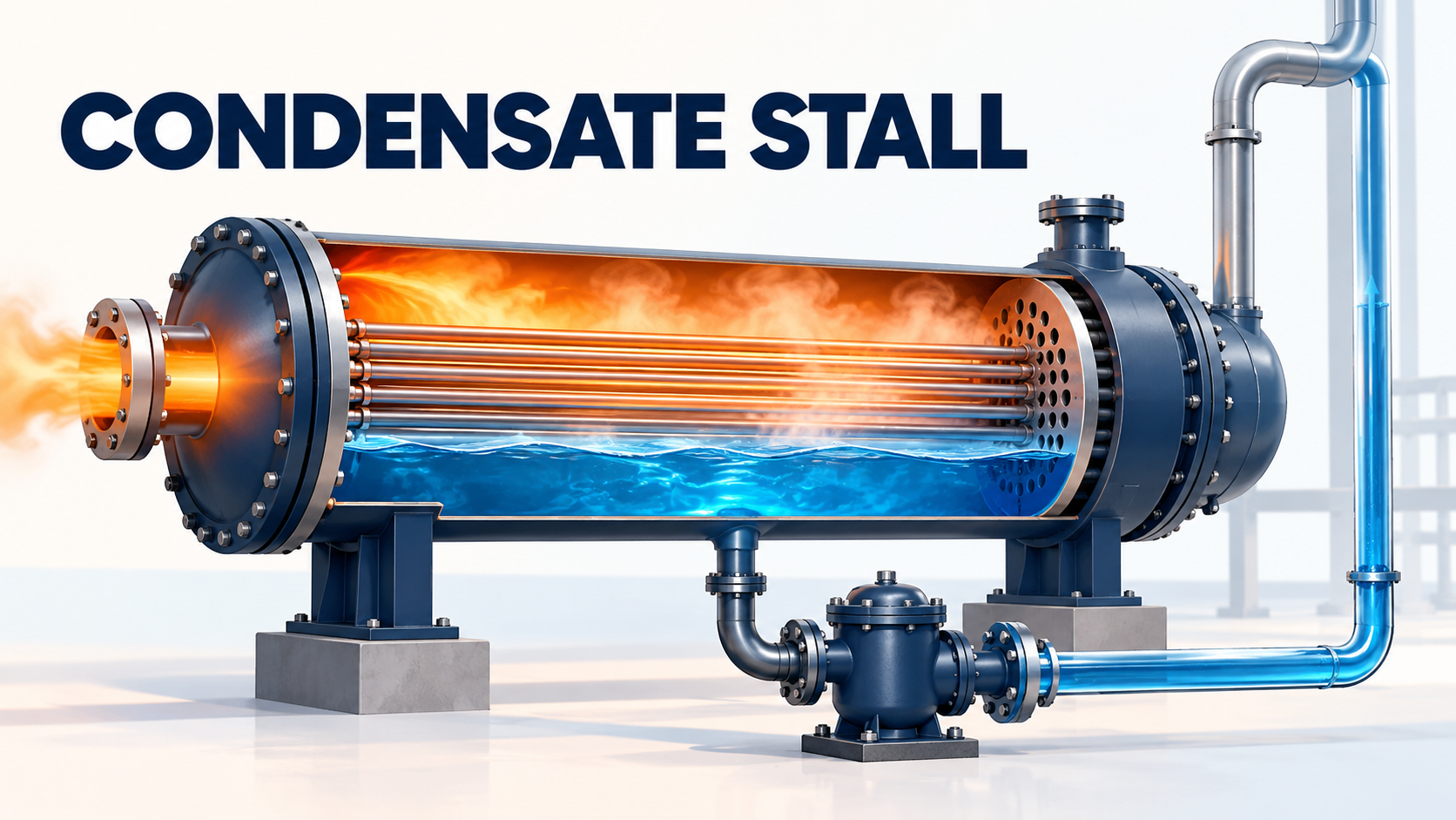
Condensate stall occurs when a heat exchanger cannot maintain enough driving pressure to discharge condensate against the return system.
A larger steam trap may reduce flow resistance, but it cannot supply pumping energy. Engineers must compare the exchanger’s actual operating pressure with return-header pressure, elevation effects, and piping losses throughout the operating range.
Where adequate differential pressure cannot be maintained, the solution may require gravity drainage to a suitable receiver or a correctly selected pump-trap arrangement.
Working Principle: Why Lower Heat Demand Can Stop Drainage
A steam-heated exchanger transfers heat as steam condenses on its heating surfaces. A modulating steam valve adjusts the heat input to maintain the required process outlet temperature.
At lower demand, the valve can reduce steam-space pressure. For saturated steam, lower pressure also means lower saturation temperature.
This pressure is measured inside the exchanger, downstream of the control valve. The steam supply header might remain at a much higher pressure.
Meanwhile, the condensate return system can impose substantial resistance. If exchanger pressure falls too far, condensate accumulates instead of draining.
Spirax Sarco’s “Heat Exchangers and Stall” explains this mechanism and identifies possible symptoms including unstable outlet temperature, control-valve cycling, waterhammer, and reduced heat output. These symptoms support investigation; none alone proves stall. (spiraxsarco.com)
The practical implication is straightforward: a system that drains successfully at maximum output may still struggle during normal turndown.
Worked Example: A Four-Metre Lift Changes the Decision
Consider this illustrative installation:
Item
Assumed value
Exchanger steam-space pressure at high load
2.0 bar(g)
Exchanger steam-space pressure at low load
0.60 bar(g)
Return-header pressure
0.30 bar(g)
Liquid-filled rise after the trap
4 m
Assumed flowing resistance of downstream components
0.10 bar
These are teaching assumptions, not operating data or recommended design limits.
For a simplified liquid-column calculation:
Static pressure = density × gravitational acceleration × height
Using an assumed condensate density of 950 kg/m³:
Static pressure = 950 × 9.81 × 4 = 37,278 Pa ≈ 0.37 bar
The estimated flowing backpressure becomes:
0.30 + 0.37 + 0.10 = 0.77 bar(g)
At high load, the approximate pressure remaining across the trap is:
2.00 − 0.77 = 1.23 bar
At low load:
0.60 − 0.77 = −0.17 bar
The low-load condition cannot sustain the assumed discharge flow.
Importantly, the 0.10-bar flowing loss decreases as flow falls. Even without it, however, the assumed header pressure plus static lift totals approximately 0.67 bar(g)—still above the available 0.60 bar(g).
The calculation therefore identifies a drainage problem that a larger trap alone cannot resolve under these assumptions.
A real assessment must account for actual liquid levels, available upstream gravity head, flashing, check-valve characteristics, and variable header pressure. This example is a screening calculation, not a complete two-phase hydraulic model.
How to Select the Drainage Arrangement
The useful comparison is between complete drainage arrangements.
Arrangement
Appropriate starting point
Main selection concern
Conventional steam trap
Positive driving pressure remains available
Capacity at each relevant operating condition
Gravity drainage to a vented receiver
Adequate elevation and suitable atmospheric collection are available
Layout, venting, and subsequent condensate transfer
Pump-trap or engineered pump-and-trap combination
Exchanger pressure can fall below return-system requirements
Motive supply, filling head, backpressure, and capacity
In a pressure-powered pump-trap arrangement, condensate can discharge through the trapping function while sufficient differential pressure exists. When it does not, a separate motive supply provides the energy needed for pumping.
Spirax Sarco’s “Practical Methods of Preventing Stall” describes gravity-drainage and pump-trap approaches. The correct choice depends on the installation; this guidance does not establish a universal product size. (spiraxsarco.com)
A vacuum breaker also has limits. It can admit air when vacuum forms and assist suitable gravity-draining installations, but it cannot provide the pressure needed to lift condensate into an elevated return main. See the manufacturer’s vacuum-breaker guidance. (spiraxsarco.com)
Piping Design: Separate Trap Sizing from Return-Line Sizing
Hot condensate can partially flash into steam when pressure falls. Consequently, a trap discharge line may carry both liquid and vapor.
Selecting that line as though it carries only liquid can underestimate its required capacity. Also, the trap connection size does not automatically determine the discharge pipe size.
Spirax Sarco’s “Sizing Condensate Return Lines” distinguishes drain lines, trap discharge lines, common returns, and pumped returns. It also warns that rising discharge lines require sufficient pressure or an appropriate pumping arrangement. (spiraxsarco.com)
For an intermittent condensate pump, check the discharge piping against the pump’s delivery rate while operating. Average condensate production can be much lower than the instantaneous pumped flow. This distinction is explained in “Layout of Condensate Return Lines”. (spiraxsarco.com)
Engineering Practice: What to Put on the Selection Sheet
The following checklist is an engineering synthesis for preparing a useful supplier inquiry:
- Define the operating cases. Include startup, maximum duty, minimum continuous duty, and changing process inlet temperatures.
- Request actual steam-space pressures. Supply-header pressure and exchanger design pressure serve different purposes.
- Document the return system. Record header-pressure variation, elevations, pipe routing, and relevant restrictions.
- State the condensate loads. Pair each load with its corresponding pressure condition.
- Check the proposed pumping arrangement. Confirm motive-pressure availability, installation height, connections, and vendor capacity data.
- Provide maintenance access. Allow room to inspect strainers, check valves, and internal components.
The distinction between design pressure and operating pressure deserves special attention. Spirax Sarco’s trap-selection example shows why the exchanger’s actual thermal performance affects the pressure available for drainage. A pressure rating alone cannot establish trap capacity. (spiraxsarco.com)
For an existing plant, collect synchronized trends of exchanger pressure, return pressure, process temperatures, and control-valve position. Compare stable operation with the conditions where heating becomes erratic.
Inspect for blockage and mechanical faults as well. Replacing a failed trap and correcting insufficient driving pressure are different maintenance decisions.
Frequently Asked Questions (FAQ)
Does a cold steam trap mean it has failed closed?
Not necessarily. A blockage, low condensate production, or insufficient driving pressure can also explain a low temperature. Check operating conditions before deciding.
Can increasing steam supply pressure solve stall?
A higher upstream pressure does not guarantee adequate pressure inside a modulating exchanger. Evaluate the controlled steam-space pressure and the process requirements.
Should every steam exchanger use a pump-trap?
No. Conventional trapping can be suitable where drainage pressure remains adequate throughout the required operating range.
Can a check valve prevent stall?
A check valve can prevent reverse flow. It cannot add the energy needed to overcome backpressure.
Conclusion
Condensate recovery and reliable heat transfer must be designed together.
Before choosing a larger steam trap, establish the pressure available inside the exchanger at low load, then compare it with the complete drainage requirement. That comparison helps determine whether the installation needs conventional trapping, a different layout, or assisted condensate removal.
The most useful selection question is: can this arrangement remove condensate in every required operating condition?
Sources
- Slipstream — Full Steam Ahead: Smart Strategies for Optimization. Listed event date: October 21, 2026. Original publication date not stated.
- Spirax Sarco — Heat Exchangers and Stall.
- Spirax Sarco — Practical Methods of Preventing Stall.
- Spirax Sarco — Gauges, Sight Glasses, Vacuum Breakers.
- Spirax Sarco — Sizing Condensate Return Lines.
- Spirax Sarco — Layout of Condensate Return Lines.
- Spirax Sarco — Example: Selecting the Trap.
The manufacturer tutorials are undated; no publication or revision dates were verified. They provide technical background rather than new announcements. No newly issued standard, revised code clause, or regulatory effective date is claimed in this article.