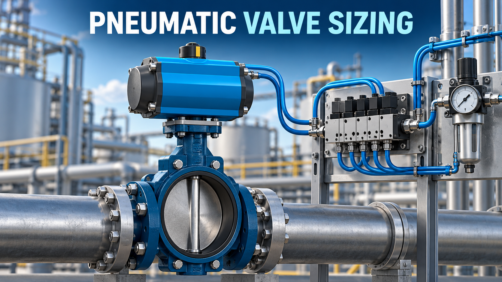
- Introduction
- Short Answer
- Pressure Produces Force; Flow Determines How Quickly Conditions Change
- Average Consumption and Required Flow Are Different
- Find the Restriction Before Upsizing the Pilot Valve
- A Practical Selection Workflow
- Faster Is Not Always Better for the Process
- Troubleshooting a Slow Pneumatic Valve
- Frequently Asked Questions (FAQ)
- Conclusion
- Sources
Introduction
An October 21, 2026 manufacturer-contributed article in IEN highlighted Emerson’s AVENTICS XV05 High Flow pneumatic valve system, reporting increased airflow capacity within an existing valve platform.
The publication date needs context: an Emerson release distributed on September 24, 2026 already described the system. The October coverage is therefore renewed attention, not evidence of a launch yesterday. No newer primary launch announcement suitable for this topic was verified.
The development raises a useful engineering question: why can a process valve move slowly even when its air-supply gauge shows the expected pressure?
The answer involves the complete pneumatic circuit. An actuator needs adequate pressure to produce force or torque, and sufficient airflow to fill and exhaust its chambers within the required time. A component’s advertised maximum flow is not a guarantee of installed valve travel time. (ien.eu, lulop.com)
Short Answer
Select the actuator and pneumatic circuit together.
Check:
- Valve torque or thrust throughout the operating stroke
- Minimum available air pressure during movement
- Required opening and closing times
- Actuator air demand
- Pilot-valve supply and exhaust capacity
- Tubing internal diameter, length and fittings
- Regulator and filter performance under flow
- Simultaneous operation of other actuators
- Required behavior after loss of power or air
A pressure gauge reading taken while nothing is moving cannot demonstrate that the system will maintain adequate pressure during actuation.
Pressure Produces Force; Flow Determines How Quickly Conditions Change
For a simple cylinder, the ideal pneumatic force depends on chamber pressure and effective piston area. In a double-acting cylinder, opposing-chamber pressure must also be considered. Friction, external load and any spring force further affect available motion.
Quarter-turn valve actuators require a torque assessment. Their output varies with pressure and actuator mechanism, so use the manufacturer’s torque curves rather than converting one nominal cylinder force into a universal valve rating.
Festo’s process-valve guidance identifies breakaway torque, operating loads and emergency conditions among the selection considerations. It also explains that pilot-valve selection depends on actuation time, tubing and pressure losses. (festo.com)
A useful distinction follows:
- Insufficient available torque: the actuator may hesitate or stop despite receiving air.
- Insufficient airflow: chamber pressure may build too slowly to achieve the required response.
- Restricted exhaust: pressure remaining in the opposing chamber can resist movement.
These conditions can coexist. Increasing header pressure may conceal a restriction without resolving its cause.
Average Consumption and Required Flow Are Different
SMC distinguishes air consumption from required airflow in its pneumatic selection tools. Consumption helps estimate usage; required flow helps size regulators and other components. Its technical guidance also includes air used by the tubing between the switching valve and actuator. (smcworld.com, smcworld.com)
Consider an illustrative duty—not data for any named product:
- Air required per stroke: 6 liters at a stated reference condition
- Required stroke duration: 0.5 seconds
- Operating frequency: 10 strokes per minute
The average consumption over a minute is:
6 × 10 = 60 reference liters/minute
The average delivery rate during each half-second stroke is:
6 ÷ 0.5 × 60 = 720 reference liters/minute
The same actuator therefore has a modest average demand but a much larger demand while moving.
This arithmetic is a screening example. It does not establish the necessary valve rating: instantaneous flow, changing chamber pressures, exhaust behavior and the manufacturer’s rating conditions still need evaluation.
Always identify the reference pressure and temperature behind terms such as NL/min, standard L/min or L/min (ANR). Do not compare catalog numbers solely because their units look similar.
Find the Restriction Before Upsizing the Pilot Valve
A larger pilot valve helps only when the rest of the circuit can support the required flow.
Festo’s flow-rate calculation tool uses inlet pressure, outlet pressure, tubing length and internal diameter as inputs. These variables explain why identical actuators can behave differently in different installations. (festo.com)
For design review, trace the complete path:
Supply: header, isolation device, filter, regulator, manifold, pilot valve, fittings, tubing and actuator port.
Exhaust: actuator port, tubing, pilot valve, speed controller, silencer and any exhaust header.
Check the actual internal passage sizes. Tubing outside diameter and nominal connection size do not fully describe flow resistance.
Festo’s VTUX engineering discussion provides a relevant manufacturer example: tubing and fittings can become the limiting elements even when the valve itself has substantial flow capacity. This is a system-design lesson, not a performance claim transferable to every installation. (festo.com)
A Practical Selection Workflow
1. Define the process requirement. Record valve differential pressure, fluid conditions, required torque or thrust, movement frequency and acceptable travel times. Opening and closing requirements may differ.
2. Establish minimum dynamic supply pressure. Use the pressure available at the package during the demanding operating case. Consider coincident actuator operation and upstream pressure losses.
3. Select the actuator. Check its output throughout the stroke, including the relevant spring-return direction where applicable. Confirm both adequate output and the valve’s allowable mechanical loads.
4. Size the complete pneumatic circuit. Evaluate pilot-valve paths, regulator capacity, tubing, fittings and exhaust components. Use manufacturer calculations or simulation when simple screening is insufficient.
5. Confirm the required failure behavior. Review loss of electrical power, loss of instrument air and restoration of supply. Accessories must support the intended action.
6. Agree on an acceptance test. Define the supply condition, valve load, timing start and finish points, and which feedback signal demonstrates completion.
These steps are practical engineering recommendations. They are not published installation details for the XV05 system.
Faster Is Not Always Better for the Process
Actuator speed is a process-design decision.
For a liquid line, changing valve position changes flow. The resulting hydraulic transient may constrain how quickly a valve should close. Conversely, a protective function may require closure within a specified time.
The appropriate question is therefore: what travel-time range satisfies the process and protection requirements?
An engineering review should reconcile actuator capability with the piping system’s permitted response. Where a transient analysis or safety-function specification governs, use that documented basis.
A quick-exhaust device, local reservoir or different control arrangement may change response substantially. Evaluate any such modification with the valve and actuator suppliers and through the project’s change-control process.
Troubleshooting a Slow Pneumatic Valve
Festo’s pressure-management guidance identifies restrictions, leaks and piping layout among causes of pressure loss. It also describes pressure monitoring as a way to detect developing problems. (festo.com)
The following observations guide investigation; none proves a diagnosis alone.
Observation
Questions to investigate
Local supply pressure falls during movement
Is upstream flow capacity adequate? Are filters or regulators restricting flow?
One direction is much slower
Do supply paths, exhaust paths, loads or speed-control settings differ?
Motion becomes slow when several valves operate
Is shared supply or exhaust capacity limiting simultaneous demand?
Actuator pressure rises but travel stalls
Is required torque higher than expected? Is there mechanical binding?
Travel completes but feedback arrives late
Is the delay in the switch, sensor adjustment or control-system processing?
Record a commissioning baseline for opening time, closing time and dynamic pressure. Compare later tests under equivalent conditions.
Frequently Asked Questions (FAQ)
Will a higher-flow pilot valve always make the actuator faster?
No. Another component may govern the response. Confirm the complete supply and exhaust paths.
Can I select the actuator from normal header pressure?
Use the minimum credible pressure available during the required movement, together with vendor selection criteria.
Does a large compressor eliminate local pressure drop?
No. Distribution piping, regulators, manifolds and small fittings can still restrict delivery.
Should the valve always close as quickly as possible?
No. Specify a travel-time requirement based on the process, piping and protective function.
Conclusion
Recent high-flow pneumatic-valve coverage highlights an enduring design issue: adequate static pressure does not establish adequate dynamic performance.
Specify the required movement, calculate the air demand and review every supply and exhaust restriction. Then verify the installed assembly under defined conditions. This produces a stronger selection basis than pressure rating or advertised airflow alone.
Sources
- IEN — High-Flow Valve Platform. Manufacturer-contributed coverage published October 21, 2026.
- Emerson release distributed through Lulop — AVENTICS XV05 High Flow. Dated September 24, 2026; establishes that the product announcement predates the October coverage.
- Festo — Process Valve Automation. Publication date not stated; accessed October 22, 2026.
- SMC — Air Consumption / Required Air Flow Capacity Calculation Software. Publication date not stated; accessed October 22, 2026.
- SMC — NCM Cylinder Technical Catalog. Used for the distinction between consumption and required airflow; publication date not independently verified.
- Festo — Flow Rate Calculation. Publication date not stated; accessed October 22, 2026.
- Festo — VTUX Valve Terminal. Publication date not stated; accessed October 22, 2026.
- Festo — Pneumatic Pressure: What It Is and How to Optimise It. Publication date not confirmed; accessed October 22, 2026.
No new standard edition or effective date is asserted in this article.