- Introduction
- Short Answer
- Why Flow Measurement Changes Pump Engineering
- Working Principle of an Electromagnetic Flow Meter
- Accuracy Specification Versus Installed Accuracy
- Comparing Common Flow Meter Technologies
- How to Select the Meter
- Engineering Practice and Maintenance
- Frequently Asked Questions (FAQ)
- Conclusion
- Sources
Introduction
A Pumps & Systems article published on October 15, 2026 highlighted an important lesson for pump engineers: selecting the pump is only part of designing a reliable fluid system. Engineers also need dependable flow measurement to confirm that the pump is operating near its intended duty point, control chemical addition, detect abnormal conditions and evaluate system performance.
This was not an announcement of a new engineering standard. It reflects a broader industry trend toward using measured operating data rather than assuming that a pump delivers the flow shown on its original datasheet.
However, purchasing a flow meter with a high accuracy specification does not automatically produce accurate field data. Pipe geometry, liquid conductivity, entrained gas, meter sizing, grounding and installation orientation can produce errors that are larger than the meter’s laboratory accuracy.
Short Answer
Select a flow meter by checking:
- The required volumetric or mass flow measurement
- Minimum, normal and maximum operating flow
- Liquid conductivity, viscosity, density and solids content
- Pressure, temperature and chemical compatibility
- Available straight pipe length and nearby disturbances
- Required accuracy, repeatability and turndown
- Pressure-loss allowance
- Output signals, diagnostics and control-system integration
- Calibration and verification requirements
- Whether the pipe will remain completely full
For conductive liquids, an electromagnetic flow meter is often attractive because it has no obstruction in the flow path and normally creates little additional pressure loss. It is unsuitable for hydrocarbons, gases and other liquids below the manufacturer’s minimum conductivity requirement.
Why Flow Measurement Changes Pump Engineering
A pump curve predicts the relationship between flow and head under specified test conditions. The actual operating point is determined by the intersection of the pump curve and the installed system curve.
Without a reliable flow measurement, engineers may know the discharge pressure but still misunderstand where the pump operates on its curve. Pressure alone cannot determine flow when valve position, fouling, liquid level or parallel-pump operation changes.
Measured flow supports several engineering decisions:
- Confirming operation near the best efficiency point
- Detecting blocked strainers and fouled heat exchangers
- Identifying an incorrectly positioned valve
- Controlling a variable-frequency drive
- Maintaining a chemical blending ratio
- Calculating transferred volume
- Comparing current performance with a commissioning baseline
- Detecting leakage or unexpected process demand
Hydraulic power can be estimated from:
[
P_h = \rho gQH
]
where:
- (P_h) is hydraulic power
- (\rho) is fluid density
- (g) is gravitational acceleration
- (Q) is volumetric flow
- (H) is pump head
If the indicated flow is 2% high while the density and calculated head are correct, the calculated hydraulic power will also be approximately 2% high. The engineer may then calculate an incorrect pump efficiency even though the pump itself has not changed.
Working Principle of an Electromagnetic Flow Meter
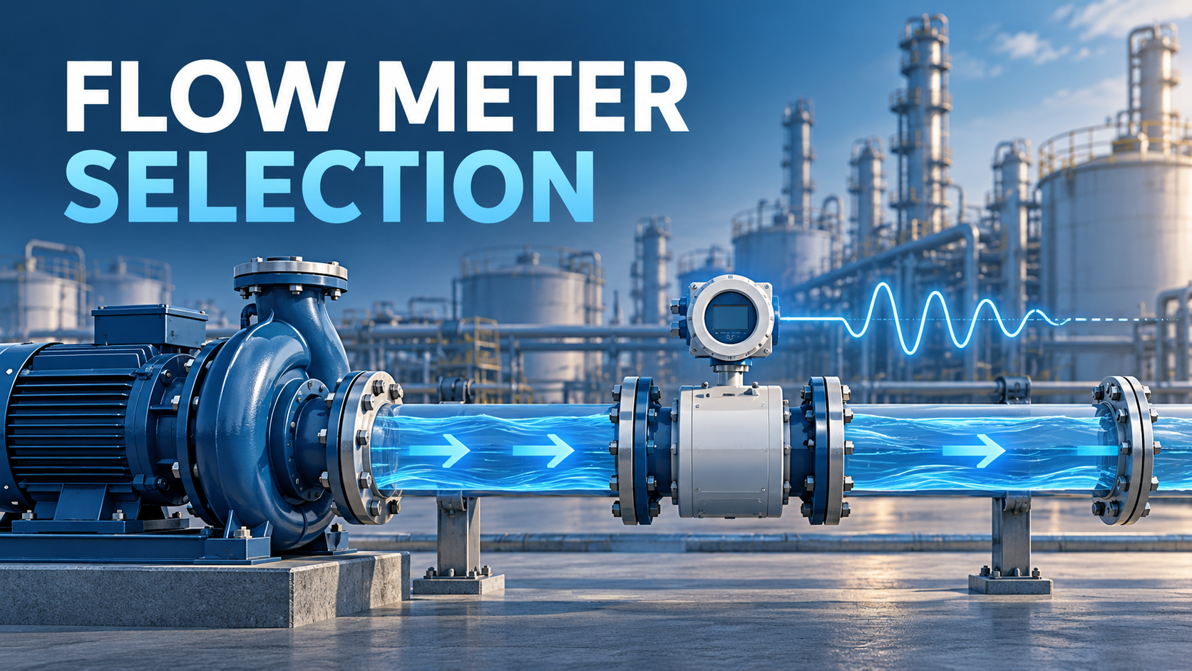
An electromagnetic flow meter applies Faraday’s law of induction. Coils create a magnetic field across an electrically insulated measuring tube. When a conductive liquid moves through this field, electrodes detect an induced voltage.
The basic relationship is:
[
U_e = BLv
]
where (U_e) is induced voltage, (B) is magnetic-field strength, (L) is the effective electrode spacing and (v) is average liquid velocity.
Because the pipe cross-sectional area is known, the transmitter calculates volumetric flow:
[
Q = Av
]
The Endress+Hauser explanation of electromagnetic flow measurement notes that the induced voltage is proportional to velocity. It also explains that each manufacturer specifies a minimum liquid conductivity.
The meter therefore needs:
- An electrically conductive liquid
- Wetted electrodes
- A completely filled measuring tube
- Suitable grounding or potential equalization
- A liner and electrode material compatible with the process
Accuracy Specification Versus Installed Accuracy
A datasheet accuracy value usually describes performance under defined reference conditions. Installed performance also depends on the application.
Distorted flow profile
Elbows, control valves, partially open isolation valves, reducers and tees can create asymmetric velocity profiles or swirl. The effect depends on the meter design, disturbance type and distance between the disturbance and sensor.
A Rosemount installation guide, for example, specifies five straight pipe diameters upstream and two downstream for the covered equipment. This is a product-specific instruction, not a universal rule for every electromagnetic meter.
Some newer products claim validated performance with shorter straight runs. Emerson’s October 8, 2026 product announcement states that its Rosemount 8795 sensor can provide 0.5% accuracy in specified zero-diameter configurations when paired with compatible transmitters and configured for the actual upstream disturbance.
That claim must not be applied to unrelated meters. The engineer should verify the exact sensor, transmitter, software option, disturbance configuration and installation limits.
Partially filled pipe
An electromagnetic meter measures velocity between its electrodes and assumes the complete pipe cross section is filled. If the pipe is only partly full, indicated volumetric flow can be seriously wrong even when both electrodes remain wetted.
Locate the meter in a low section, an upward-flowing vertical pipe or another arrangement that maintains a full measuring tube. Use empty-pipe detection when available, but do not treat the alarm function as a substitute for proper piping design.
Incorrect meter size
Selecting the meter only from the nominal line size can place normal flow near the lower end of the measuring range. A smaller meter may improve velocity and measurement resolution, but reducers add pressure loss and must be evaluated hydraulically.
Check velocity at minimum, normal and maximum flow:
[
v = \frac{4Q}{\pi D^2}
]
Compare the results with the manufacturer’s published operating range and application guidance.
Comparing Common Flow Meter Technologies
Technology
Suitable applications
Main advantages
Key limitations
Electromagnetic
Conductive liquids, water, many chemicals and slurries
Unobstructed bore, low pressure loss, no moving parts
Requires minimum conductivity and a full pipe
Coriolis
Liquids requiring direct mass flow and density measurement
Direct mass flow, high accuracy, no long straight run in many applications
Higher cost, weight and possible pressure loss
Ultrasonic
Water systems, large pipes and retrofit measurement
Clamp-on options available, no process penetration
Performance depends on pipe condition, fluid and installation
Differential pressure
Liquids, gases and steam
Mature technology and broad service range
Permanent pressure loss and impulse-line maintenance
Positive displacement
Clean, viscous liquids and batching
Good low-flow measurement
Moving parts and sensitivity to contamination
No single technology is best for every service. Required measurement, fluid properties and installed conditions should drive the choice.
How to Select the Meter
1. Define the measurement purpose
State whether the signal is for indication, control, custody transfer, pump protection, energy calculation or condition monitoring. A local indicator and a closed-loop chemical dosing system may require different accuracy, response time and verification levels.
2. Build a complete process data sheet
Include minimum, normal and maximum flow rather than one design value. Record pressure, temperature, density, viscosity, conductivity, vapor pressure, solids, gas content and chemical concentration.
3. Check wetted materials
For an electromagnetic meter, evaluate the liner, electrodes, grounding rings and gaskets separately. Compatibility can change with concentration and temperature. Avoid selecting materials from the chemical name alone.
4. Review the piping arrangement
Identify elbows, pumps, tees, control valves, reducers and strainers near the proposed location. Compare the actual arrangement with the manufacturer’s approved installation configurations.
Provide access for transmitter operation, grounding checks, removal and calibration. Consider whether the transmitter should be mounted remotely because of vibration, flooding, high temperature or poor accessibility.
5. Evaluate the complete measurement uncertainty
Separate accuracy from repeatability. Repeatability helps detect operational changes, while absolute accuracy is important for material balance and performance testing.
Include uncertainty from the flow meter, pressure instruments, temperature instruments, density assumptions and data acquisition when calculating pump efficiency.
Engineering Practice and Maintenance
Treat the flow signal as one part of a condition-monitoring system. A flow change becomes more useful when compared with discharge pressure, suction pressure, motor power, speed, valve position and vibration.
For example:
- Lower flow plus higher differential pressure across a filter suggests fouling.
- Lower flow plus reduced suction pressure may indicate suction restriction.
- Lower flow at unchanged speed and valve position can indicate system blockage or pump deterioration.
- Higher power without a corresponding increase in hydraulic output requires investigation.
- An abrupt flow step without changes in pressure or power may indicate an instrument problem.
Record a baseline after commissioning. The baseline should include operating mode, pump combination, speed, valve positions and process conditions. Without this context, historical trends may compare different system states.
Periodically inspect grounding, electrode coating, empty-pipe alarms, diagnostic messages and signal stability. Verification functions can support maintenance decisions, but their scope and acceptance criteria should be documented.
Frequently Asked Questions (FAQ)
Can an electromagnetic flow meter measure oil?
Normally no. Most oils and hydrocarbons do not have enough electrical conductivity. Consider Coriolis, positive-displacement, ultrasonic or other technologies after checking the application.
Should the flow meter be installed before or after the pump?
The discharge side is often easier because it normally remains pressurized and full. Avoid locations affected by entrained air, severe pulsation or unstable flow. The manufacturer’s installation instructions and the process arrangement should determine the final location.
Does a 0D flow meter eliminate every installation concern?
No. A product may be validated for specific upstream disturbances and configurations. Full-pipe conditions, grounding, conductivity, material compatibility and correct setup still apply.
Can flow measurement prove that cavitation is occurring?
Flow reduction can support the diagnosis, but it does not prove cavitation by itself. Engineers should also examine suction pressure, available NPSH, noise, vibration, temperature and pump performance.
Is the most accurate meter always the best selection?
No. A meter with slightly lower laboratory accuracy may provide better field performance if it suits the fluid, flow range and piping arrangement. Maintainability, pressure loss, diagnostics and lifecycle cost also matter.
Conclusion
Recent attention to flow measurement reinforces a practical pump-engineering principle: the operating point should be measured rather than assumed.
Select the meter from the measurement purpose, fluid properties and full operating range. Then verify installation geometry, meter sizing, full-pipe conditions, grounding and material compatibility. Accurate flow data can improve control and pump assessment, but only when the instrument and piping are engineered as one system.
Sources
- Pumps & Systems — “Beyond the Pump: The Value of Accurate Flow Measurement,” published October 15, 2026
- Emerson — Rosemount 8795 Magnetic Flow Sensor announcement, published October 8, 2026
- Emerson — Rosemount 8732E Magnetic Flowmeter System Quick Start Guide, document revision CD, June 2013
- Endress+Hauser — Understanding Electromagnetic Flowmeters: Measuring Principle, Construction and Application Limits
- Hydraulic Institute — Improving the Efficiency of Pumping Systems Through Pump System Optimization, published May 22, 2024