- Introduction
- Short Answer
- Working Principle: Three Different Sources of Error
- Worked Example: Estimate the Transport Time
- Use Actual Flow in the Calculation
- Preserve the Sample While Conditioning It
- How to Select Regulators, Filters, Pumps, and Valves
- Verify the Whole Sample Path
- Maintenance: Investigate Changes Before Recalibrating
- Frequently Asked Questions (FAQ)
- Conclusion
- Sources
Introduction
A gas analyzer measures the sample that reaches its measurement cell. If that sample arrives late or changes composition during transport, an accurate sensor can still provide an unsuitable process reading.
Engineering.com coverage dated October 27, 2026 highlighted Emerson’s Rosemount QX1400 analyzer. However, Emerson’s original announcement is dated October 1. The recent article is renewed coverage, rather than a newly verified launch. (engineering.com, emerson.com)
The manufacturer describes combined laser and paramagnetic measurement technologies with hazardous-area installation options. It also identifies a practical opportunity: in suitable applications, locating the analyzer closer to the sampling point can shorten the sample transport system.
That connection matters beyond this product. Analyzer location, tubing volume, pressure, and conditioning determine how useful a measurement becomes for process decisions.
Short Answer
Specify the analyzer and its sampling system together.
A successful system must deliver a sample that is:
- Representative of the intended process stream
- Suitable for the analyzer’s inlet requirements
- Available within an acceptable measurement delay
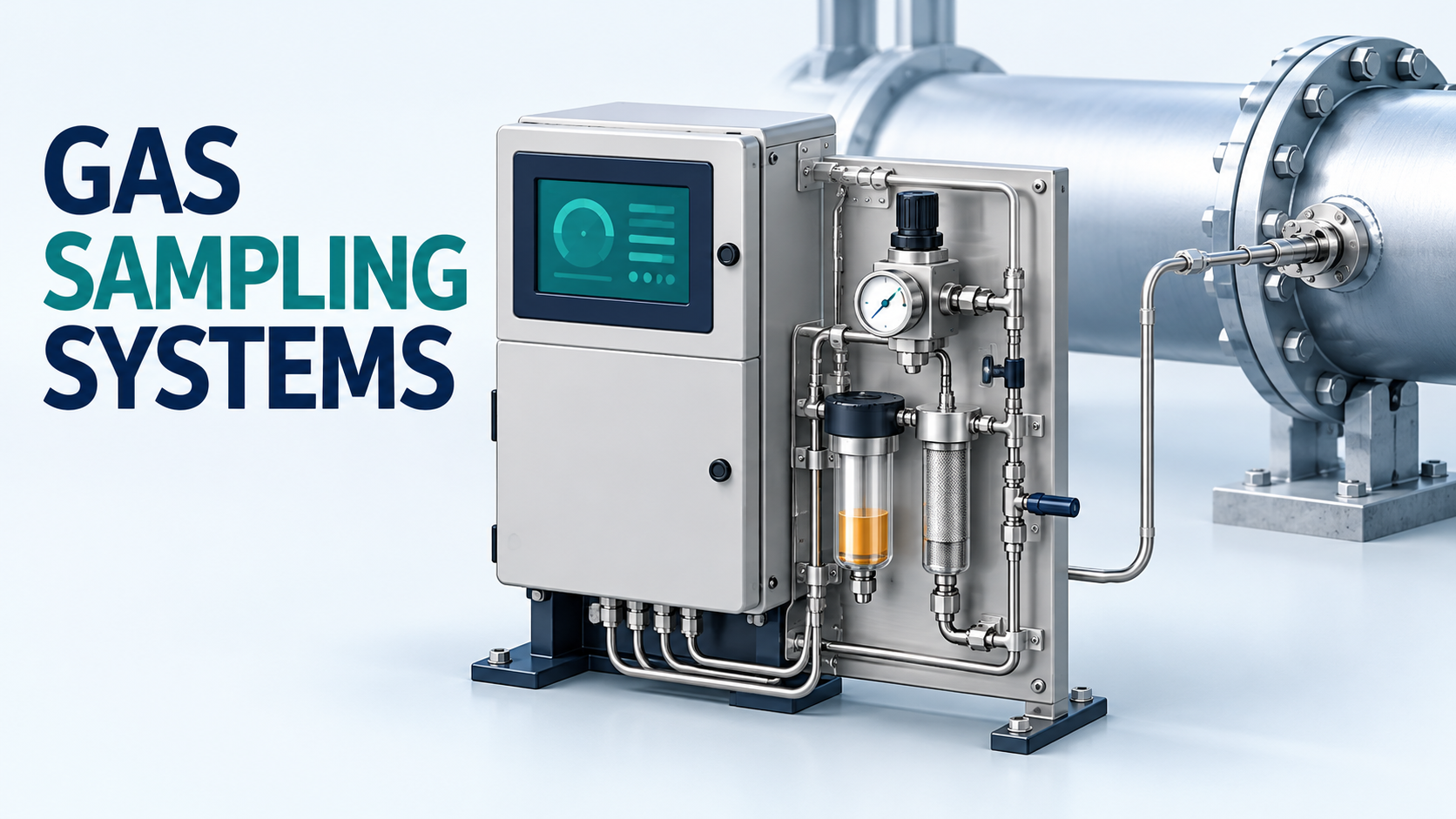
Review the sample tap, probe, tubing, regulators, filters, pumps, switching valves, and discharge destination. Sensor accuracy alone cannot establish the performance of that complete path.
Working Principle: Three Different Sources of Error
It helps to separate three questions:
Question
Example problem
Is the analyzer measuring correctly?
Calibration drift
Is the sample composition preserved?
Condensation removes part of the gas mixture
Does the reading represent the required time?
A long transport line delivers an old sample
These problems need different remedies.
Recalibrating the analyzer may address instrument error. It does not remove an upstream liquid pocket or shorten a transport line.
Swagelok’s guidance on analytical-system delay identifies delay contributions throughout the process connection, transport, conditioning, switching, and analysis stages. The acceptable delay must be determined from the process application. (swagelok.com)
For example, a slowly changing quality measurement and a rapidly changing process-control measurement may need different response specifications.
Worked Example: Estimate the Transport Time
Consider a hypothetical gas sample line:
Input
Assumed value
Tubing length
30 m
Internal diameter
4 mm
Actual gas volume flow inside the line
1.0 L/min
Assume approximately constant pressure and temperature along the line, with single-phase gas and steady flow.
The internal volume is:
Volume = π × internal diameter² × length ÷ 4
= π × 0.004² × 30 ÷ 4
= 0.000377 m³ = 0.377 L
A simple nominal residence-time estimate is:
Time = volume ÷ actual volume flow
= 0.377 L ÷ 1.0 L/min
= 0.377 min ≈ 22.6 seconds
Now consider a different proposed route: 60 m of tubing with a 6 mm internal diameter, at the same actual flow.
Volume = π × 0.006² × 60 ÷ 4
≈ 1.696 L
Nominal residence time ≈ 101.8 seconds
The second line contains approximately 4.5 times as much gas volume. At the assumed flow, its nominal transport time is also 4.5 times greater.
These are original teaching examples, not design limits or results for a named analyzer.
The calculation excludes filters, vessels, mixing, adsorption, and the analyzer’s own response. It estimates residence time; it does not establish the complete system’s response to a concentration change.
Use Actual Flow in the Calculation
A common calculation error is dividing line volume by a flow stated at a reference condition.
For gas, actual volume flow depends on pressure and temperature. A value in standard litres per minute cannot automatically be treated as litres per minute inside a pressurized tube.
Identify:
- Reference pressure and temperature
- Actual line pressure and temperature
- Whether the flow indication is actual or reference-based
- Whether changing conditions require a compressibility correction
Use absolute pressure in gas-volume conversions.
Likewise, nominal tubing size does not establish internal volume. Use the actual bore, accounting for wall thickness.
Smaller tubing reduces volume at a fixed actual flow, but it also changes pressure loss. The design must establish a feasible flow and pressure profile rather than minimizing diameter in isolation.
Preserve the Sample While Conditioning It
The sample must meet the analyzer’s permitted pressure, temperature, flow, and contamination limits.
However, making a sample mechanically acceptable can change what it represents.
Swagelok’s representative-sampling guidance identifies dead spaces, adsorption, contamination, chemical reactions, and partial phase changes as possible causes of composition error. Condensation can divide a mixture into phases with different compositions. (swagelok.com)
This leads to an important distinction:
Preventing unintended condensation preserves a gas sample.
Deliberately removing moisture creates a conditioned sample whose reporting basis must be understood.
If drying forms part of the specified measurement method, confirm how the result relates to the required wet or dry basis. Also investigate whether the conditioning step could remove the target component.
A filter or knockout pot should therefore be selected for a defined purpose. Adding one without reviewing composition effects and internal volume can introduce a new measurement problem.
How to Select Regulators, Filters, Pumps, and Valves
The following checklist is an engineering synthesis for preparing a sampling-system inquiry.
Pressure regulators:
Establish inlet conditions, required outlet pressure, flow range, and the effect of pressure reduction on temperature and phase behavior.
Filters and liquid separators:
Define the contamination to be removed, acceptable pressure drop, internal volume, drainage arrangement, and maintenance access.
Sample pumps:
Where a pump is required, assess inlet pressure, gas composition, wetted materials, leakage, and discharge conditions. Consider whether operating the upstream sample path below atmospheric pressure increases the significance of air ingress.
Switching valves:
Review internal volume, purge behavior, cross-stream leakage, and the time required to obtain a stable reading after switching.
Flow-control devices:
Confirm the actual operating flow and pressure basis. Record the effect of changing filter resistance or downstream pressure.
Swagelok’s calibration and switching module description illustrates how pressure, temperature, flow, filtration, and stream selection are combined in a subsystem. Its product features are manufacturer statements, not a universal configuration for every application. (products.swagelok.com)
Verify the Whole Sample Path
A calibration check at the analyzer inlet tests a different boundary from a check introduced farther upstream.
Test location
What the check can help assess
Analyzer inlet
Analyzer response and local connections
Conditioning-system inlet
Analyzer plus the included conditioning path
Approved upstream test connection
More of the transport and conditioning system
The precise interpretation depends on which components the test actually includes.
For commissioning, agree on a suitable step-response procedure, stable operating conditions, test-gas compatibility, and acceptance criteria. Record both the initial delay and the time to reach the specified fraction of the final response.
Swagelok’s sampling-delay inspection guidance reinforces the need to examine the probe, transport, conditioning, and analyzer together. (swagelok.com)
A successful local calibration should not be presented as proof that the entire upstream sample path performs correctly.
Maintenance: Investigate Changes Before Recalibrating
Useful baseline records include sample flow, relevant pressures, conditioning temperatures, filter differential pressure, and response-test results.
If readings become slow or unstable, compare those conditions with the baseline.
A restriction may reduce sample flow. A temperature change may affect phase behavior. A leaking connection may introduce contamination. A recently modified valve arrangement may add trapped volume.
These are investigation paths, not diagnoses from a single symptom.
Retain tubing dimensions and component details in the maintenance documentation. A replacement filter with a much larger internal volume can affect response even when its pressure rating and filtration grade appear suitable.
Frequently Asked Questions (FAQ)
Does a faster analyzer eliminate sample delay?
No. Transport and conditioning delays remain.
Should the analyzer always be installed beside the sample tap?
Evaluate the complete installation, including environmental conditions, access, utilities, and applicable hazardous-area requirements.
Can I use a flowmeter’s standard-flow reading directly in volume divided by flow?
Only after confirming that the volume and flow use compatible pressure and temperature conditions.
Does clear, dry gas guarantee a representative sample?
No. Composition can also be affected by adsorption, leakage, contamination, or the conditioning method.
Conclusion
A useful gas measurement depends on the entire sampling path.
Calculate transport volume, use the correct flow basis, preserve the intended composition, and verify response through the relevant components. These steps connect analyzer specifications to the process information that operators actually need.
Sources
- Engineering.com — Emerson Releases QX1400 for Certified Hazardous Locations. Coverage dated October 27, 2026.
- Emerson — QX1400 Gas Analyzer Announcement. Original release dated October 1, 2026.
- Swagelok — Understanding and Measuring Time Delay.
- Swagelok — Maintaining a Representative Sample.
- Swagelok — Four Areas to Inspect When Measuring Time Delay.
- Swagelok — Calibration and Switching Modules.
Swagelok page publication dates were not verified. Sources checked October 28, 2026. No new standard edition or regulatory effective date is asserted. The numerical examples are illustrative.