- Introduction
- Short Answer
- What EN 17955 Covers—and What It Does Not
- The Safety Function Includes More Than the Valve
- Start with the Required Safe State
- Worked Example: Valve Travel Time Is Only Part of the Response
- Connect Valve Selection to Process and Piping Conditions
- Partial Stroke Testing Has a Specific Purpose
- Engineering Practice: Make the Evidence Reviewable
- Frequently Asked Questions (FAQ)
- Conclusion
- Sources
Introduction
A valve certificate provides useful evidence for equipment selection. It does not demonstrate that an installed safety function will detect a hazard and stop the process correctly.
An October 16, 2026 manufacturer-sourced article highlighted Richter’s valve portfolio assessed against IEC 61508 and EN 17955. The underlying certification listing can be checked directly: exida lists several Richter ball-valve series against both standards. (chemengonline.com, exida.com)
No suitable new announcement was verified within the preferred seven-day window. This article therefore uses that recent certification coverage to explain an enduring engineering issue: component qualification and application suitability are different decisions.
For students and beginner engineers, the practical task is to connect the certificate to the process duty, complete valve assembly, and maintenance plan.
Short Answer
Select a shutdown valve against a clearly defined safety function.
Establish what must happen, how quickly it must happen, and under which process conditions. Then confirm that the valve, actuator, accessories, installation, and testing arrangements support that requirement.
A SIL capability statement is one input. It does not replace:
- Process hazard assessment
- Mechanical and chemical suitability
- Actuator sizing
- Complete-function verification
- Defined inspection and proof testing
Also check the scope and limitations of the specific certificate and associated safety documentation.
What EN 17955 Covers—and What It Does Not
The BSI catalog entry for BS EN 17955:2024 identifies the subject as functional safety of safety-related automated valves. It lists publication on August 31, 2024.
Its public scope describes evaluation of mechanical items in a final element, including valves, actuators, and assemblies. It also states that intended use must be known. Electrical and electronic components are assessed under EN 61508. Manually operated valves and certain other protective devices, including pressure relief valves outside this functional-safety approach, are excluded. (knowledge.bsigroup.com)
This helps avoid a terminology trap: a shutdown valve in an instrumented protective function is not interchangeable with a pressure relief valve.
The BSI date is the publication date of its national adoption. It is not a universal legal effective date. This article does not infer detailed requirements from an unreviewed standards text.
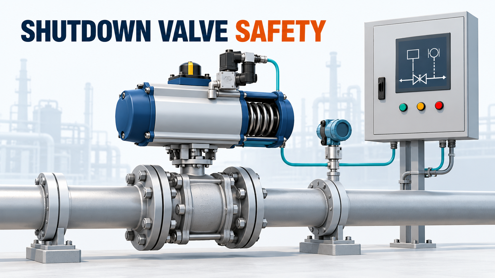
The Safety Function Includes More Than the Valve
Consider a hypothetical high-pressure trip:
A pressure measurement initiates a logic decision, which commands an automated valve to stop incoming flow.
The required action depends on several connected elements:
Element
Example question
Measurement
Can the hazardous condition be detected?
Logic solver
Is the correct trip action generated?
Pilot and actuator
Can the command produce the required movement?
Valve
Can it achieve the required flow restriction or isolation?
Supporting utilities
Are necessary air and electrical supplies addressed?
The UK Health and Safety Executive’s control-system guidance explains that elements and utilities required for the safety function belong in the safety-related system. It also cautions that subsystem SIL claims do not eliminate verification of the complete function. (hse.gov.uk)
At the lifecycle level, IEC 61511-1:2016+AMD1:2017 addresses specification, design, installation, operation, and maintenance of process-sector safety instrumented systems. IEC lists this consolidated publication as Edition 2.1, published August 16, 2017. (webstore.iec.ch)
These references answer different questions: one concerns mechanical equipment evaluation; the other concerns the process safety system throughout its life.
Start with the Required Safe State
“Fail closed” is useful shorthand, but insufficient as a complete specification.
For a real application, define:
- Which stream must be interrupted
- Whether closing, opening, or another action achieves the required state
- Required response time
- Permitted leakage, where relevant
- Pressure, temperature, and fluid conditions during the demand
- Expected behavior after loss and restoration of utilities
The following is an engineering interpretation: a closed-position signal confirms the position being detected. It does not, by itself, measure leakage through the seat.
Likewise, an actuator that reaches its stop during a workshop test has not automatically demonstrated the required action under maximum process differential pressure.
The performance requirement must describe the process result, not merely the movement command.
Worked Example: Valve Travel Time Is Only Part of the Response
Suppose a hypothetical safety specification requires the defined protective action within 5.0 seconds.
Assume the timing review assigns:
Contribution
Illustrative time
Measurement and detection
0.3 s
Logic processing and output
0.1 s
Pilot switching delay
0.2 s
Actuator and valve travel to the required position
3.8 s
Total
4.4 s
The arithmetic is:
0.3 + 0.1 + 0.2 + 3.8 = 4.4 seconds
The difference from the assumed requirement is:
5.0 − 4.4 = 0.6 seconds
These are teaching assumptions, not recommended response times or data for a certified product.
The example shows why a valve travel-time result cannot represent the complete trip response.
It also does not establish that the design passes. The review must consider uncertainty, operating conditions, timing definitions, and when the process actually reaches the required safe state. Some actions may overlap; other delays may need inclusion.
A tighter timing budget may require changes elsewhere in the function, rather than simply a faster actuator.
Connect Valve Selection to Process and Piping Conditions
The following checklist is a practical engineering synthesis.
Check chemical compatibility.
Review the body, lining, seats, seals, and other wetted components against the actual fluid and temperature.
Check mechanical duty.
Provide the relevant differential pressures, operating direction, fluid condition, and expected deposits or solids. Obtain the valve supplier’s required torque or thrust basis.
Check the complete assembly.
Identify the actuator, coupling, bracket, pilot, tubing, switches, and other accessories included in the evaluated configuration.
Check the piping response.
For liquid service, the proposed closing behavior may need a transient review. A short travel time is not automatically the correct process requirement.
Check installation and access.
Allow inspection, testing, isolation, and removal without depending on an impractical maintenance arrangement.
A certificate should be matched to the exact configuration and intended service. Similar model names or connection sizes are not enough to establish equivalence.
Partial Stroke Testing Has a Specific Purpose
Partial stroke testing moves the valve through part of its travel. It can reveal certain movement-related faults while limiting process disturbance.
It cannot independently demonstrate every property of a complete shutdown, including full travel and required seat performance.
An exida explanation published October 16, 2013 shows that partial-stroke and subsequent proof-test coverage can overlap. Once a failure mode is detected by one test, it must not be counted again as an independently detected failure in the verification model. Its numerical example is application-specific and should not be transferred to another valve. (exida.com)
The practical lesson is to connect each test step to the failure modes it can reveal.
A full movement test should not automatically be described as complete proof testing either. The procedure and claimed coverage must match the safety analysis.
Engineering Practice: Make the Evidence Reviewable
Before purchase approval, assemble a package containing:
- The required safety action and operating envelope
- The exact valve and actuator configuration
- Applicable certificate and assessment references
- Supplier safety instructions and restrictions
- Mechanical sizing and response-time evidence
- The proposed test method and acceptance criteria
- Responsibilities for installation, validation, and maintenance
During operation, retain results in a form that supports comparison: test conditions, measured response, observed defects, repairs, and restoration checks.
Changing the actuator, pilot arrangement, tubing, or test procedure may alter assumptions used in the original verification. Review those changes against the established safety requirements.
Frequently Asked Questions (FAQ)
Does a SIL 3 listing make the whole shutdown function SIL 3?
No. The listing concerns defined equipment and assessment conditions. The complete function requires its own verification.
Is a spring-return actuator enough to guarantee closure?
No. Available output, mechanical condition, process loads, and the installed arrangement still matter.
Can partial stroke testing replace every other test?
No. Its value depends on the failure modes detected and the testing assumptions used in the verification.
Is the fastest closing valve always preferable?
No. The required response must satisfy both the protective function and the process constraints.
Conclusion
A shutdown valve must perform a defined action under defined conditions.
Use certification evidence alongside process requirements, mechanical selection, assembly details, and a workable testing plan. That connection turns a component capability claim into evidence for an installed protective function.
Sources
- Chemical Engineering — Valve Portfolio Certified for Functional Safety Applications. Manufacturer-sourced coverage published October 16, 2026.
- exida — Richter KN / KNR / KNA / KK / KA / KH / BVA Listing. Lists IEC 61508 and EN 17955; page publication date not stated.
- BSI — BS EN 17955:2024. BSI publication date: August 31, 2024.
- IEC — IEC 61511-1:2016+AMD1:2017 CSV. Edition 2.1, published August 16, 2017.
- UK HSE — Control Systems. Used for system-boundary and verification principles; publication date not stated.
- exida — Why Does My Proof Test Coverage Change with Partial Stroke Testing?. Published October 16, 2013.
Sources checked October 27, 2026. Public scopes and listings were reviewed; no unreviewed standard clauses, universal test intervals, or new regulatory effective dates are asserted.