- Introduction
- Short Answer
- Working Principle: Select the Relief Path
- Inlet Pressure Loss Includes More Than the Changeover Valve
- Worked Example: A Component Can Fit While the Installation Fails
- The Outlet Path Must Follow the Selected Inlet
- Equipment Selection: Request Evidence for the Assembly
- Maintenance Isolation Requires Its Own Verification
- Standards: Confirm the Project Basis
- Frequently Asked Questions (FAQ)
- Conclusion
- Sources
Introduction
Baker Hughes’ valve website lists an October 30, 2026 news item introducing the Consolidated SafeSwitch changeover valve. The announcement itself is dated October 2026 and describes maintaining overpressure protection while one safety relief valve is inspected, tested, repaired, or replaced. October 30 is the website listing date; an exact first-launch day was not established. (valves.bakerhughes.com, valves.bakerhughes.com)
The practical engineering question is important: does installing a second relief valve actually leave a usable relief path during maintenance?
The answer depends on more than valve count. The selected path needs adequate capacity, acceptable inlet losses, an available discharge route, and a workable isolation arrangement.
The manufacturer’s announcement describes intended functionality. It does not independently validate a particular plant installation.
Short Answer
Review a relief-valve changeover arrangement as a complete protective system.
Confirm that:
- The selected relief path provides the required relieving capacity.
- The changeover mechanism maintains an adequate path during movement.
- Total inlet pressure loss satisfies the applicable design basis.
- The active valve has an available discharge route.
- The maintenance branch can be isolated, depressurized, and verified.
- Operators can identify and secure the intended operating position.
A standby valve supports availability only when these conditions remain satisfied.
Working Principle: Select the Relief Path
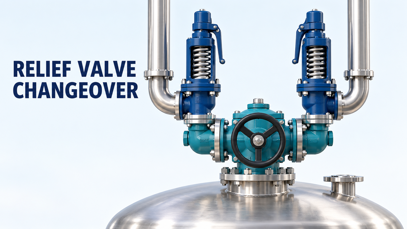
A typical arrangement connects a protected vessel to a changeover valve, which directs the inlet toward one of two safety relief valves.
One relief valve remains connected to the protected system while the other branch is taken out of service.
Spirax Sarco’s installation guidance describes this maintenance arrangement and emphasizes maintaining the flow passage during changeover. Farris Engineering’s changeover-valve catalogue likewise describes designs intended to prevent simultaneous isolation of both relief devices. These descriptions apply to purpose-designed equipment, not every three-way valve. (spiraxsarco.com, cw-valvegroup.com)
Do not assume that an ordinary selector valve provides equivalent protection.
Also distinguish redundancy from shared capacity. If two relief valves must operate together to meet the required duty, removing either one may leave insufficient capacity. A one-duty, one-standby arrangement needs each selected path to satisfy its assigned relief requirement.
Inlet Pressure Loss Includes More Than the Changeover Valve
When a relief valve opens, fluid must travel from the protected equipment through its inlet connection.
That path can include a vessel nozzle, pipe, fittings, reducers, and the changeover valve.
The LESER changeover-valve catalogue explicitly includes the selector and connected piping in the inlet pressure-loss calculation. It also notes that different calculation diameters require careful treatment of loss coefficients. (leser.com)
Consequently, a low-loss selector does not establish a low-loss installation.
The flow basis matters as well. Use the relieving conditions and flow basis required by the applicable design method and valve supplier. Normal process flow is not automatically the relevant condition.
For compressible or flashing service, do not substitute a simple incompressible-water calculation without establishing its suitability.
Worked Example: A Component Can Fit While the Installation Fails
Consider a hypothetical installation with:
- Relief-valve set pressure: 10 bar(g)
- An assumed project inlet-loss criterion: 3% of set pressure
- Component losses evaluated at the agreed relief-flow condition
The assumed allowable loss is:
10 × 0.03 = 0.30 bar
Suppose the calculated losses are:
Inlet-path component
Illustrative pressure loss
Vessel connection and entrance
0.05 bar
Pipe and fittings
0.08 bar
Changeover valve
0.18 bar
Reducer
0.03 bar
Total
0.34 bar
The selector alone contributes 1.8% of set pressure. However, the complete path contributes:
0.34 ÷ 10 × 100 = 3.4%
Under the assumed project criterion, the installation exceeds the allowance by 0.04 bar.
These are original teaching values, not SafeSwitch specifications or results for another product.
The 3% value appears in manufacturer installation guidance, including Spirax Sarco’s discussion. Its applicability and calculation basis must be checked for the actual valve, service, governing requirements, and any permitted engineering analysis. It is not presented here as a universal rule without exceptions.
The lesson is to approve the complete inlet path, rather than a component percentage in isolation.
The Outlet Path Must Follow the Selected Inlet
Some installations also use an outlet changeover valve so both relief valves can connect to a common discharge system.
This creates another coordination requirement.
If the inlet selects relief valve A while the outlet blocks A’s discharge, the installation does not provide the intended protection simply because B remains physically installed.
Spirax Sarco describes synchronization of inlet and outlet selectors. Farris also describes mechanically linked combinations for this purpose. The exact arrangement and operating instructions remain product-specific.
For design review, trace each complete path:
Protected equipment → selected inlet → relief valve → selected outlet → discharge destination
Repeat the check for each permitted operating position and the transition between them.
Then evaluate discharge pressure and backpressure under relevant conditions. A shared header may be affected by other relieving devices, so checking an isolated branch alone may be insufficient.
These are system-level engineering checks, not claims that a particular linkage eliminates every failure mode.
Equipment Selection: Request Evidence for the Assembly
A useful supplier inquiry should identify the protected equipment, fluid, relieving scenarios, required capacity, temperatures, pressure conditions, and discharge destination.
Request evidence addressing:
Selection issue
Evidence to review
Relief capacity
Suitability of each selected relief path
Inlet hydraulics
Loss data and calculation basis
Transition behavior
Available passage throughout changeover
Materials
Compatibility with process and cleaning conditions
Position control
Indication, locking, and linkage arrangements
Maintenance
Isolation limitations and approved instructions
Consider deposits, crystallization, or other service conditions that could obstruct movement or passages.
Also review supports and access. The arrangement must permit maintenance without imposing unacceptable loads on the vessel connection or making isolation devices inaccessible.
These recommendations are an engineering synthesis for reviewing the installation.
Maintenance Isolation Requires Its Own Verification
Selecting the standby relief valve does not prove that the maintenance branch is safe to open.
Residual pressure may remain. Isolation may leak. A common outlet may expose the branch to pressure from elsewhere.
The UK Health and Safety Executive’s HSG253, The Safe Isolation of Plant and Equipment, published in 2006, provides guidance for selecting and managing process isolations. Its detailed guidance addresses testing isolation effectiveness and warns that blocked drains can give misleading depressurization results. (hse.gov.uk, hse.gov.uk)
A maintenance plan should therefore define:
- Which relief path remains available
- The isolation boundary on both sides of the equipment
- How trapped contents and pressure are managed
- How isolation effectiveness is demonstrated
- How the arrangement is restored and checked
The acceptable isolation method depends on the fluid, equipment, work, and site requirements. A selector position indication alone does not establish a sufficient maintenance barrier.
This article explains the design questions; it is not a live-system switching procedure.
Standards: Confirm the Project Basis
API’s public announcement identifies API 520 Part II, Seventh Edition, covering installation of pressure-relieving devices. It also identifies an engineering-analysis approach for evaluating installation suitability. (api.org)
That public summary does not replace the applicable standard text.
Confirm the edition, amendments, jurisdictional requirements, and project specifications before approving the arrangement. No new November 2026 requirement or universal legal effective date is asserted here.
Frequently Asked Questions (FAQ)
Can a standard three-way valve replace a purpose-designed changeover valve?
Only if its suitability is demonstrated for the protective function, including passage availability and all permitted positions. Similar connections are insufficient evidence.
Does a standby valve eliminate shutdowns?
It may support online maintenance of a relief valve. Work on common piping or the selector itself can still require shutdown.
Does low selector pressure loss prove compliance?
No. Evaluate the complete inlet path using the applicable flow and calculation basis.
Does switching prove the isolated branch is depressurized?
No. Isolation and residual pressure require separate verification.
Conclusion
A relief-valve changeover system must preserve a complete, adequate relief path while making maintenance manageable.
Check capacity, inlet losses, outlet availability, transition behavior, and isolation together. Those interfaces determine whether the standby valve provides useful protection when the duty valve is unavailable.
Sources
- Baker Hughes — SafeSwitch Changeover Valve Announcement. Announcement dated October 2026; manufacturer news listing dated October 30, 2026.
- Spirax Sarco — Safety Valve Installation. Manufacturer engineering guidance; publication date not stated.
- LESER — Change-over Valves, Types 330 and 320. Manufacturer catalogue; publication date not verified.
- Farris Engineering — Changeover Valves, Models 320B and 370B. Catalogue 0815C, copyright 2015.
- HSE — The Safe Isolation of Plant and Equipment, HSG253. Published 2006; full guidance.
- API — API 520 Part II, Seventh Edition Announcement. Public scope announcement; publication date not stated on the reviewed page.
Sources checked November 1, 2026. Numerical examples are illustrative. No unreviewed standard clauses or application-specific approval are asserted.