- Introduction
- Short Answer
- Working Principle: Two Levels Create a Stable Operating Band
- Worked Example: Estimate Pump Cycling from Tank Volume
- Why a Larger Pump Can Increase Cycling
- Select the Measurement and Pump Together
- Wireless Control Needs a Definition of Valid Data
- A Control Function Is Not Automatically a Safety Function
- Commissioning: Test the Sequence and the Failure Cases
- Frequently Asked Questions (FAQ)
- Conclusion
- Sources
Introduction
On October 27, 2026, OleumTech announced SIMPLE LOGIC, a control solution integrated into its BreeZ 8 configuration software for local and wireless automation across supported OTC networks. The company describes a drag-and-drop interface that reduces the need for conventional programming. (prnewswire.com)
Processing Magazine subsequently highlighted the product on October 30. The original announcement falls within the expanded seven-day search window; no suitable distinct announcement was verified within the preferred 48 hours. (processingmagazine.com)
For beginning engineers, the practical lesson is straightforward: easier configuration does not define the correct process behavior.
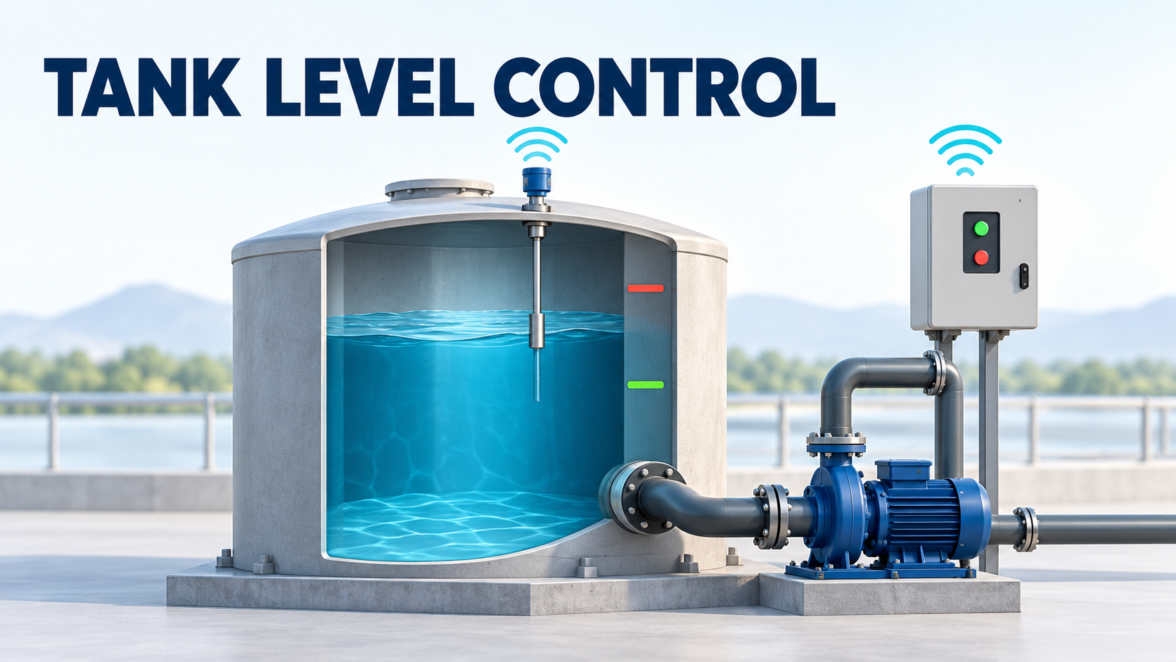
A tank-drainage pump provides a useful example. Before arranging logic blocks, engineers must establish when the pump starts, when it stops, what prevents excessive cycling, and what happens when a measurement or communication link fails.
Short Answer
Write the operating sequence and failure responses before configuring the controller.
For a tank-drainage application, define:
- Start and stop levels
- Pump capacity at the actual system duty
- Required permissives and protective actions
- Treatment of invalid or outdated measurements
- Behavior after power or communication loss
- Local and remote control priorities
- Evidence required during commissioning
The software announcement establishes available functionality. It does not demonstrate that a particular installation meets its process or safety requirements.
Working Principle: Two Levels Create a Stable Operating Band
For simple pump-out control, the pump starts at an upper level and stops at a lower level.
Between those thresholds, the previous operating state is retained:
- A stopped pump remains stopped while the tank fills.
- A running pump continues draining until the stop level is reached.
This separation is commonly called a hysteresis band.
If the same threshold repeatedly starts and stops the pump, small level fluctuations can produce frequent switching. Separate thresholds provide a usable storage volume between commands.
Grundfos’s LC 231 installation and operating instructions describe separate start and stop settings, signal-detection timing, and delay functions intended to address frequent starts and stops. These are product-specific implementation options, rather than universal settings for every pump. (api.grundfos.com)
Hysteresis and delay solve different problems. Hysteresis establishes a level band; a delay changes when an action occurs after a condition is detected. Either can affect the available margin before overflow or low-level operation.
Worked Example: Estimate Pump Cycling from Tank Volume
Consider a hypothetical collection tank with:
Input
Assumed value
Constant horizontal tank area
10 m²
Difference between start and stop levels
0.30 m
Constant incoming flow
12 m³/h
Pump discharge flow while running
30 m³/h
These are original teaching assumptions, not recommended settings.
The volume between the two levels is:
10 × 0.30 = 3 m³
While the pump is stopped, the tank fills at 12 m³/h:
Filling time = 3 ÷ 12 = 0.25 h = 15 minutes
While the pump runs, incoming water continues entering. The net drainage rate is therefore:
30 − 12 = 18 m³/h
The time to return from the start level to the stop level is:
Draining time = 3 ÷ 18 ≈ 0.167 h = 10 minutes
One complete cycle takes approximately:
15 + 10 = 25 minutes
The estimated start frequency is:
60 ÷ 25 = 2.4 starts per hour
This is an idealized steady-state result. It excludes startup transients, changing inflow, varying pump flow, sensor filtering, and delays.
It must also be checked against the pump and motor manufacturer’s permitted operating conditions.
Why a Larger Pump Can Increase Cycling
Keeping the same example, suppose the selected pump delivers 48 m³/h instead of 30 m³/h.
The net drainage rate becomes:
48 − 12 = 36 m³/h
The draining time becomes:
3 ÷ 36 ≈ 0.083 h = 5 minutes
Filling still takes 15 minutes, so the cycle becomes 20 minutes:
60 ÷ 20 = 3 starts per hour
Under these assumptions, the larger pump empties the operating band faster and starts more frequently.
This does not mean smaller pumps are always preferable. Maximum incoming flow, emergency storage, downstream capacity, and the required recovery time still matter.
It does show why pump capacity and tank operating volume should be selected together.
If incoming flow equals or exceeds pump discharge, the running pump cannot lower the level in this simplified model. No adjustment to the start threshold fixes that capacity shortfall.
Select the Measurement and Pump Together
The required control behavior influences equipment selection.
For the level instrument, review range, measurement uncertainty, response, mounting, fluid properties, and credible disturbances such as foam or turbulence.
For the pump, establish the actual duty across the operating range. Tank level changes suction conditions, while downstream pressure and valve positions can change discharge flow.
The stop level must respect the pump’s installation requirements. Depending on the arrangement, these may involve submergence, suction conditions, or dry-running limitations.
For piping and valves, review isolation, backflow prevention where needed, maintenance access, and the effect of restrictions on pump capacity.
These are engineering review questions. The numerical example does not establish minimum submergence, suction margin, or a permissible number of starts for a real installation.
Wireless Control Needs a Definition of Valid Data
OleumTech’s product page lists math, logic, limits, counters, timers, and flow functions, with local and wireless control execution on supported hardware. Those capabilities do not establish a universal communication-failure response. (oleumtech.com)
A displayed value can remain plausible after its source stops updating.
The following is a proposed engineering review matrix, not a description of SIMPLE LOGIC’s configured defaults:
Condition
Question to resolve
Normal measurement
Is the value within range and updating as expected?
Outdated measurement
At what age is the value no longer acceptable for control?
Communication loss
Which actions continue locally, and which are inhibited?
Power restoration
Is automatic restart permitted, and under what conditions?
Conflicting commands
Which local, remote, and protective commands take priority?
There is no universally correct choice between stopping and continuing.
Stopping a drainage pump can allow a tank to fill. Continuing without reliable level information can expose the pump or downstream process to other problems.
Choose the response from the process consequences and available protective measures, then verify that the hardware and configuration implement it.
A Control Function Is Not Automatically a Safety Function
Normal level control and protection against a hazardous overflow may have different requirements.
The UK HSE’s control-system guidance discusses margins between normal and safe operating conditions, independence, reliability, and common-cause failures in safety-related systems. Its general principles support examining the complete protective arrangement, rather than assuming that another software block provides independent protection. (hse.gov.uk)
For example, two functions using the same level transmitter may share the consequences of that transmitter failing.
Determine whether additional protection is required through the project’s hazard assessment. The product announcement alone does not establish safety certification or suitability for a credited protective function.
Commissioning: Test the Sequence and the Failure Cases
Begin with a written cause-and-effect description that can be checked against the installed configuration.
Test normal filling and draining, but also verify:
- Behavior between the start and stop thresholds
- Response to invalid or unavailable measurements
- Communication interruption and recovery
- Local and remote mode changes
- Power loss and restoration
- Commanded operation versus actual pump feedback
Agree on expected results before testing.
Record configuration versions, settings, test conditions, observed behavior, and unresolved deviations. A successful screen demonstration does not establish that the motor, pump, piping, and feedback behave correctly together.
Configuration access also deserves attention. NIST SP 800-82 Revision 3, published September 28, 2023, provides operational-technology security guidance while recognizing performance, reliability, and safety needs. (csrc.nist.gov)
An engineering application of that principle is to control configuration changes and retain a verified recovery copy. Revision 3 is the document referenced here; no new regulatory effective date is asserted.
Frequently Asked Questions (FAQ)
Can a delay replace separate start and stop levels?
Some controllers support such arrangements, but the resulting cycle and level margins still require evaluation.
Does a wireless link have to carry every control action?
No. Establish the division between local execution and network-dependent functions from verified hardware capabilities and process requirements.
Should communication loss always stop the pump?
No universal response applies. Evaluate the consequences of stopping and continuing.
Does drag-and-drop configuration remove the need for testing?
No. It changes how logic is created, not the need to verify installed behavior.
Conclusion
Reliable remote level control begins with a process definition.
Calculate the usable tank volume, check pump capacity and cycling, define valid-data rules, and specify failure responses. Then configure and test the complete installation.
The useful outcome is an operating sequence that remains understandable when conditions change.
Sources
- OleumTech — SIMPLE LOGIC Launch Announcement. Company-issued release, October 27, 2026.
- OleumTech — SIMPLE LOGIC Product Information. Primary capability description; publication date not stated.
- Processing Magazine. Product coverage listed October 30, 2026.
- Grundfos — LC 231 Dual Pump Unit Installation and Operating Instructions. Product-specific control guidance; document revision date not verified.
- UK HSE — Control Systems. Used for general safety-system principles; publication date not stated.
- NIST — SP 800-82 Revision 3, Guide to Operational Technology Security. Final publication, September 28, 2023.
Sources checked November 2, 2026. Calculations are illustrative; no application-specific control settings, safety-integrity claim, or manufacturer performance guarantee is asserted.