- Introduction
- Short Answer
- Working Principle: One Feed Stream Becomes Two Streams
- Worked Example: Concentrating 50 Litres to 10 Litres
- Why a 10 L/min Pump Does Not Finish This Batch in Four Minutes
- Transmembrane Pressure Is Different from Channel Pressure Drop
- More Pressure Is Not Always the Solution
- Select the Pump, Valves, and Tubing as One System
- Commissioning and Maintenance: Keep the Measurements Separate
- Frequently Asked Questions (FAQ)
- Conclusion
- Sources
Introduction
A pump displaying a high flow rate does not necessarily mean a membrane system will finish a batch quickly.
Manufacturer-published coverage dated November 2, 2026 introduced CPC Biotech’s Quattroflow HTX pump drive, highlighting updated controls, calibration, and interfaces for laboratory and bioprocessing applications. The announcement includes small-scale filtration among its applications. (fluidhandlingpro.com)
The manufacturer’s product page confirms that displayed flow can be calculated from motor speed and adjusted through a calibration routine. That functionality should be distinguished from an independent measurement of liquid passing through a membrane. (cpc-bio.com)
This distinction matters in tangential flow filtration, or TFF. Engineers must separate circulation flow, permeate production, and membrane pressure conditions before selecting the pump and estimating processing time.
Short Answer
A TFF circulation pump moves liquid along the membrane. Only part of that liquid passes through it.
Track three different quantities:
- Circulation flow: liquid delivered through the membrane feed channel.
- Permeate flow: liquid passing through the membrane.
- Transmembrane pressure: the pressure difference driving passage across the membrane.
Use circulation requirements to assess the pump duty. Use demonstrated permeate flux and membrane area to estimate throughput. Check pressure limits and product behavior across the complete operating range.
Working Principle: One Feed Stream Becomes Two Streams
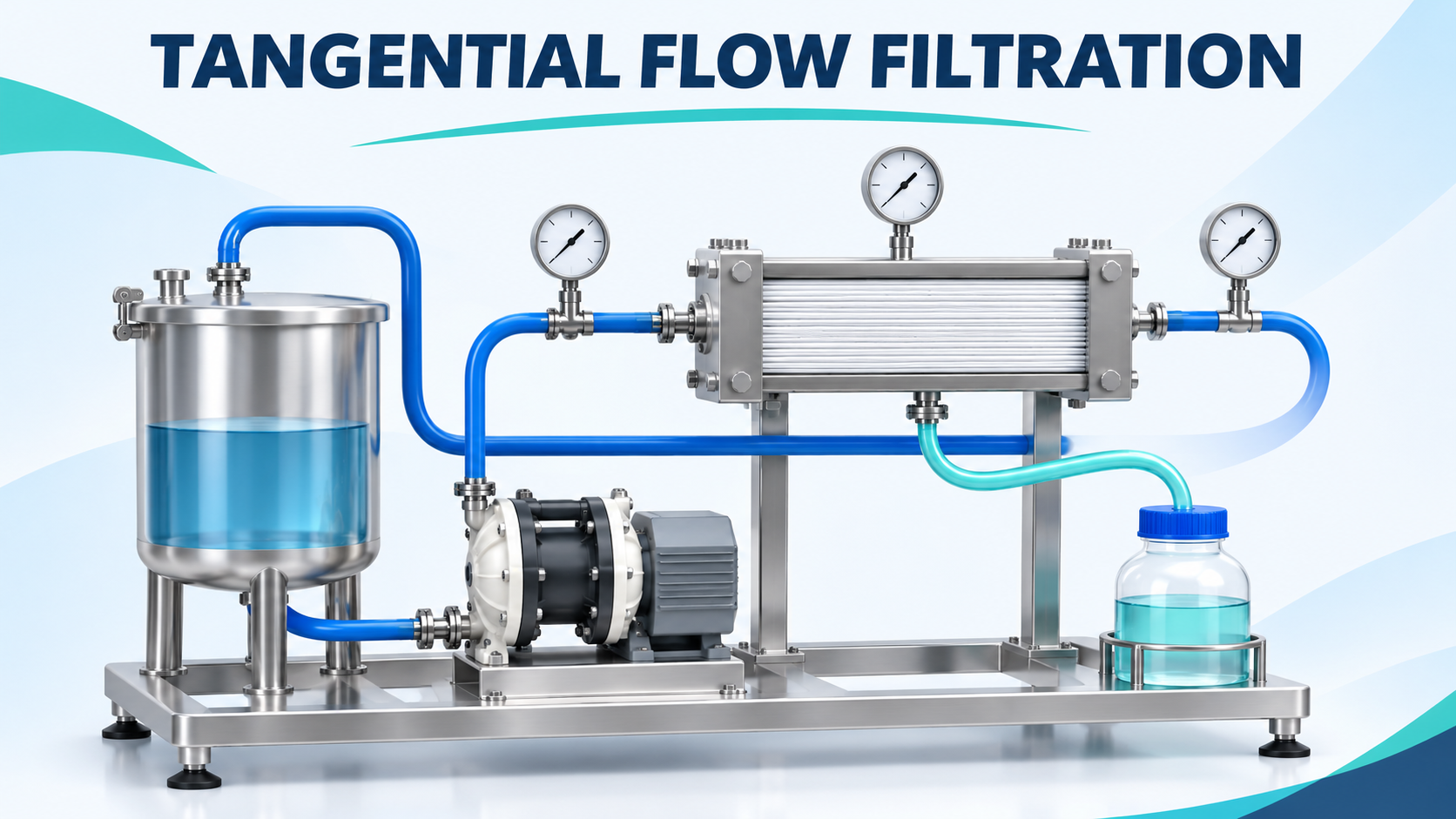
In a recirculating TFF system, liquid travels from a reservoir through a pump and into the membrane module.
Inside the module, the stream divides:
- Permeate passes through the membrane.
- Retentate continues along the feed channel and returns to the reservoir.
Cytiva’s TFF operating guidance distinguishes crossflow along the membrane from pressure-driven flow through it. Crossflow helps limit accumulation at the surface, while membrane selection determines which components are preferentially retained. (cdn.cytivalifesciences.com)
For a product-concentration application, the desired material may remain in the retentate as liquid leaves through the permeate connection.
However, retention is application-specific. A membrane’s nominal classification alone does not establish product recovery or the final separation result.
Worked Example: Concentrating 50 Litres to 10 Litres
Consider a hypothetical batch:
Input
Assumed value
Initial liquid volume
50 L
Initial retained-solute concentration
10 g/L
Final liquid volume
10 L
Membrane area
0.50 m²
Constant permeate flux
60 L/(m²·h)
Assume complete retention of the solute, no sampling or recovery losses, no added liquid, and negligible system hold-up for this simplified calculation.
The initial solute mass is:
50 L × 10 g/L = 500 g
If that mass remains in the final 10 L:
500 g ÷ 10 L = 50 g/L
The volume concentration factor is:
50 ÷ 10 = 5
The required permeate removal is:
50 − 10 = 40 L
Calculate permeate flow from flux and area:
60 L/(m²·h) × 0.50 m² = 30 L/h
Therefore, the idealized processing time is:
40 L ÷ 30 L/h ≈ 1.33 hours = 80 minutes
These are original teaching assumptions, not a recommended operating recipe or performance claim for Quattroflow equipment.
Real flux can change during concentration. The 80-minute result therefore depends on the assumed constant flux actually being sustained.
Why a 10 L/min Pump Does Not Finish This Batch in Four Minutes
Now suppose the circulation pump delivers 10 L/min at the membrane inlet.
It would be incorrect to calculate:
40 L ÷ 10 L/min = 4 minutes
That uses circulation flow as though it were permeate flow.
In the example, permeate production is:
30 L/h ÷ 60 = 0.50 L/min
Ignoring accumulation within the module, the corresponding retentate flow is approximately:
10 − 0.50 = 9.50 L/min
Most liquid returns to the reservoir and passes through the module repeatedly.
This distinction affects equipment selection. The pump must deliver the required circulation against system resistance, while the collection system and batch-time estimate depend on permeate production.
A larger circulation pump may influence membrane performance, but it does not automatically increase permeate production in direct proportion to its rated capacity.
Transmembrane Pressure Is Different from Channel Pressure Drop
A commonly used estimate of average transmembrane pressure, or TMP, is:
TMP = (feed pressure + retentate pressure) ÷ 2 − permeate pressure
The feed-channel pressure drop is:
Channel pressure drop = feed pressure − retentate pressure
Cunha and colleagues’ original research, first published September 25, 2023, describes this average-pressure definition and investigates how pressure varies inside a membrane module. An average TMP is therefore a useful system quantity, rather than a complete description of local conditions. (aiche.onlinelibrary.wiley.com)
Consider these illustrative readings, all using the same gauge-pressure reference:
Measurement
Assumed pressure
Feed
3.0 bar(g)
Retentate
1.0 bar(g)
Permeate
0.2 bar(g)
Then:
TMP = (3.0 + 1.0) ÷ 2 − 0.2 = 1.8 bar
Meanwhile:
Channel pressure drop = 3.0 − 1.0 = 2.0 bar
These values describe different physical directions: across the membrane versus along its feed channel.
They are teaching values, not acceptable pressure limits for a particular membrane, tubing assembly, or product.
More Pressure Is Not Always the Solution
A decline in permeate flow can tempt an operator to increase pressure.
However, membrane behavior also depends on concentration, viscosity, temperature, surface accumulation, and the particular separation.
Sartorius’s TFF guidance describes the interaction between flow, TMP, and gel-layer formation. These conditions require application-specific optimization. (sartorius.com)
Endress+Hauser’s concentration-process guidance likewise explains that excessive TMP can accelerate fouling rather than resolve declining flux. (us.endress.com)
The engineering response is to compare operating trends before changing the setpoint.
For example, ask whether permeate flow declined while concentration increased, whether temperature changed, and whether circulation remained within its established range. A single low-flow reading does not identify the cause.
Select the Pump, Valves, and Tubing as One System
The following is an engineering review framework, not a universal equipment specification.
Pump duty: Define circulation flow and required differential pressure throughout the batch. Include the expected final fluid condition, rather than considering only the dilute starting solution.
Fluid compatibility: Check pump chambers, diaphragms, tubing, seals, connectors, and instruments against process and cleaning conditions.
Product suitability: Establish acceptable exposure to shear, temperature, and repeated circulation through appropriate testing.
Control valves: Identify which valve controls retentate backpressure and how its movement affects the system. Endress+Hauser describes retentate-side restriction as a conventional means of managing TMP; the exact control arrangement remains system-specific.
Pressure protection: Review credible blocked-flow conditions, equipment ratings, alarms, and the required protective response. A configurable alarm does not independently establish adequate protection.
Tubing layout: Balance pressure loss, hold-up, drainage, access, and the mechanical requirements of the selected assembly.
Commissioning and Maintenance: Keep the Measurements Separate
A useful baseline includes circulation flow, feed and retentate pressures, permeate pressure, permeate production, temperature, and batch volume.
For a timed permeate collection:
Permeate flow = collected volume ÷ collection time
If mass is measured instead, use an appropriate density when converting to volume.
Compare that result with the pump display only after identifying what the display represents. A calibrated speed-based calculation and a permeate collection measure different streams.
For reusable systems, Cytiva’s guidance discusses normalized water permeability as a baseline for membrane assessment and cleaning evaluation. Follow the selected membrane’s instructions; do not transfer a cleaning procedure from another product.
Record test conditions so later comparisons distinguish equipment changes from changes in fluid or operating conditions.
Frequently Asked Questions (FAQ)
Does doubling circulation flow halve processing time?
Not automatically. Processing time depends on permeate production and the changing batch conditions.
Can permeate pressure be assumed to be zero?
Only when the actual arrangement justifies that assumption. Collection piping or imposed backpressure can matter.
Does fivefold volume concentration guarantee fivefold product concentration?
Only under the simplified complete-retention and no-loss assumptions. Actual recovery must be established.
Is the pump’s displayed flow the filtration rate?
Usually it describes pump delivery or its calculated estimate. Identify the measurement location and basis.
Conclusion
TFF selection begins by separating circulation from filtration.
Calculate the required permeate removal, estimate throughput from supported flux data, and distinguish TMP from channel pressure loss. Then select and verify the pump, valves, tubing, and instruments against the complete concentration process.
Sources
- CPC Biotech via Fluid Handling Pro — Quattroflow HTX Launch Coverage. Published November 2, 2026.
- CPC Biotech — Quattroflow HTX Pump Drive Series. Primary product information; publication date not stated.
- Cytiva — TFF Operating Guidance and Ultrafiltration Fundamentals. Document marking CY46090-29Jan25-PO, copyright 2025.
- Cunha et al. — Intramodule Pressure Profiles and Protein Accumulation During Tangential Flow Filtration. First published September 25, 2023.
- Sartorius — Tangential Flow Filtration. Manufacturer technical guidance; publication date not stated.
- Endress+Hauser — Concentration by TFF. Manufacturer process guidance; publication date not stated.
Sources checked November 4, 2026. Numerical examples are illustrative. No universal flux, pressure limit, cleaning recipe, or new regulatory requirement is asserted.