- Introduction
- Short Answer
- Working Principle: Transfer Heat Without Sharing Coolant
- Worked Example: Equal Heat Duty Does Not Mean Equal Flow
- Coolant Properties Affect More Than the Heat Balance
- Pump Differential Pressure Is Different from Equipment Pressure Rating
- Valves and Controls Must Preserve the Operating Envelope
- Maintenance: Trend Hydraulic, Thermal, and Chemical Conditions Together
- Frequently Asked Questions (FAQ)
- Conclusion
- Sources
Introduction
On October 28, 2026, HEXONIC announced technical selection support for heat exchangers in data center coolant distribution units. The announcement addresses the interface between facility cooling water and the coolant circulating through IT equipment. It describes an application-support offering, rather than independently demonstrated energy savings or a newly validated cooling technology. (accessnewswire.com)
This news connects directly to familiar plant engineering work. A liquid-to-liquid coolant distribution unit, or CDU, combines heat transfer, circulation, instrumentation, and control across two separate fluid systems.
The important design question is broader than exchanger capacity: can each circuit deliver the required cooling while maintaining suitable pressure, cleanliness, and operating conditions?
This article focuses on that interface. The same reasoning applies when industrial cooling systems separate a sensitive equipment loop from a larger utility-water network.
Short Answer
Specify the facility loop and technology loop separately, then verify how they work together.
For each loop, establish:
- Fluid composition and temperature range
- Required flow and allowable pressure loss
- Operating and design pressures
- Materials and cleanliness requirements
- Control, isolation, and maintenance arrangements
The exchanger transfers heat between the loops. It does not make their flows, pressures, or water-quality requirements identical.
Working Principle: Transfer Heat Without Sharing Coolant
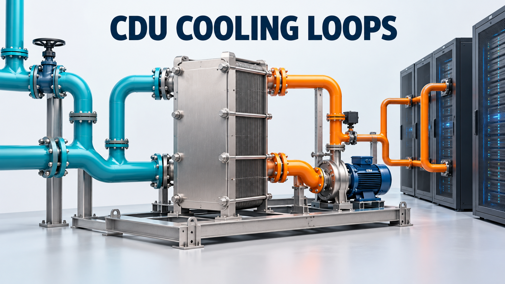
In a liquid-to-liquid CDU, warmed technology coolant passes through one side of a heat exchanger. Cooler facility water passes through the other side and carries the transferred heat toward the building’s heat-rejection equipment.
HEXONIC’s application description identifies the exchanger as the component that transfers thermal energy without directly mixing the fluids. The surrounding CDU manages coolant temperature, flow, and pressure. (hexonic.com)
This separation has a practical purpose. Facility water suitable for a building cooling network may not satisfy the requirements of server cold plates, hoses, connectors, and other sensitive components.
The ASHRAE TC 9.9 white paper Water-Cooled Servers: Common Designs, Components, and Processes explains the value of separating facility-water and technology-cooling water-quality domains. The reviewed publication is dated 2019, with corrections dated October 10, 2019 incorporated. It is technical guidance, not a newly effective regulation. (ashrae.org)
Separation also creates an engineering boundary: both sides require their own specifications.
Worked Example: Equal Heat Duty Does Not Mean Equal Flow
Consider a hypothetical CDU transferring 500 kW.
For this teaching example, assume both circuits contain water with:
- Specific heat capacity: 4.18 kJ/(kg·K)
- Density: 1,000 kg/m³
- Negligible heat loss to the surroundings
Use the steady-state heat balance:
Heat duty = mass flow × specific heat capacity × temperature change
Suppose the technology coolant enters the exchanger at 40°C and leaves at 30°C.
Its required mass flow is:
500 ÷ (4.18 × 10) ≈ 11.96 kg/s
The corresponding volume flow is:
11.96 ÷ 1,000 × 3,600 ≈ 43.1 m³/h
Now suppose facility water enters at 20°C and leaves at 25°C.
Its required mass flow is:
500 ÷ (4.18 × 5) ≈ 23.92 kg/s
Its volume flow is approximately:
86.1 m³/h
Circuit
Assumed temperature change
Calculated water flow
Technology coolant
10 K
43.1 m³/h
Facility water
5 K
86.1 m³/h
Both sides transfer the same heat, but the facility side requires twice the flow under these assumptions.
These are original illustrative calculations, not specifications for a commercial CDU. They establish a heat balance; they do not establish the required exchanger area or prove thermal performance.
The practical lesson is to calculate both sides before selecting connections, pumps, control valves, and flow instruments.
Coolant Properties Affect More Than the Heat Balance
Real technology coolant may contain glycol, corrosion inhibitors, or other additives.
Changing the fluid can change density, heat capacity, viscosity, and thermal conductivity. A selection calculated for water should therefore be reviewed before substituting another coolant.
The Open Compute Project’s Modular Technology Cooling System for “Cloud Scale”, Version 1.0, dated August 25, 2025, discusses coolant compatibility with wetted materials and the effects of fluid properties on system design. It is industry guidance; its publication date is not a legal effective date. (opencompute.org)
For a supplier inquiry, identify the coolant formulation and concentration, not simply “water/glycol.”
Then obtain fluid properties across the relevant temperature range. A cold-start condition can present different hydraulic behavior from normal operation.
Compatibility review should cover the complete wetted path: exchanger, pump, seals, valves, hoses, connectors, instruments, and cleaning chemicals.
Pump Differential Pressure Is Different from Equipment Pressure Rating
A circulation pump must provide enough differential pressure to overcome the resistance of its circuit.
KSB’s engineering explanation of head distinguishes pump head from system head and relates head to the energy transferred to the fluid. (ksb.com)
Consider this hypothetical technology-loop pressure-loss budget at its required flow:
Component group
Assumed pressure loss
CDU heat exchanger
60 kPa
Distribution piping and fittings
40 kPa
Rack equipment and connections
90 kPa
Other inline components
30 kPa
Total
220 kPa
For water, 220 kPa corresponds to approximately 22.4 m of head.
That is an illustrative circulation requirement. It is not the maximum pressure that every component may experience.
Equipment pressure ratings must also account for the applicable pressurization arrangement, elevation, pump shutoff conditions, temperature, and credible operating events.
Likewise, the exchanger’s pressure loss along one circuit is different from the pressure difference acting across its separating plates.
Review conditions where one side remains pressurized while the other is drained or isolated. The exchanger supplier needs those cases when confirming mechanical suitability.
Valves and Controls Must Preserve the Operating Envelope
The following are engineering checks for developing the installation, rather than requirements quoted from a particular standard.
Define the controlled variable. Establish how the system maintains technology-coolant supply temperature and sufficient flow to connected equipment.
Check variable-load behavior. Rack demand can change without an identical change in facility-water conditions. Review minimum flow, control range, and the interaction of pump and valve commands.
Specify isolation boundaries. Determine which exchanger, pump, filter, or branch can be removed from service and what cooling remains available.
Review blocked-in sections. Assess whether trapped liquid can experience unacceptable pressure during temperature changes and provide protection where required.
Plan filling and venting. Air remaining after maintenance can disrupt circulation and make commissioning results difficult to interpret.
More pump capacity cannot compensate for every thermal limitation. If facility water is too warm for the required technology-coolant supply temperature, the thermal design and operating strategy need review.
Maintenance: Trend Hydraulic, Thermal, and Chemical Conditions Together
Endress+Hauser’s cooling-fluid monitoring guidance identifies pH, conductivity, and turbidity as useful indicators of coolant condition. It also emphasizes the relationship between fluid quality and flow. The page’s publication date was not verified. (at.endress.com)
These measurements support investigation; none independently proves that the entire cooling system is healthy.
A practical commissioning baseline should include:
- Inlet and outlet temperatures on both exchanger circuits
- Flow on both sides
- Relevant pressures and differential pressures
- Pump speed and control-valve position
- Coolant identification and agreed chemistry results
Compare operating data at similar loads and conditions.
For example, rising pressure loss at unchanged flow may justify checking for restriction. Deteriorating temperature performance may involve facility-water conditions, changing load, reduced flow, fouling, or measurement error.
Use the combined evidence before assigning a cause or ordering chemical cleaning.
Frequently Asked Questions (FAQ)
Must both sides of the exchanger use the same coolant?
No. Fluid separation allows different formulations, subject to thermal, mechanical, and compatibility checks.
Does a 500 kW rating establish suitability?
Only when its stated temperatures, flows, fluids, pressure losses, and other selection conditions match the required duty.
Does low exchanger pressure loss mean low operating pressure?
No. Pressure loss and the pressure contained by the equipment are different quantities.
Can conductivity alone demonstrate coolant quality?
No. Interpret it against the specified formulation and other relevant chemical and contamination indicators.
Conclusion
A CDU is an interface between two fluid systems with different responsibilities.
Calculate each circuit’s flow, distinguish circulation pressure loss from mechanical pressure limits, and specify coolant compatibility across every wetted component. Then verify the integrated controls and establish a useful maintenance baseline.
That approach connects an exchanger selection to reliable cooling at the equipment.
Sources
- HEXONIC — Heat Exchanger Selection Support for Data Center CDU Applications. Company-issued announcement, October 28, 2026.
- HEXONIC — CDU Liquid Cooling in Data Centers. Manufacturer application explanation; publication date not stated.
- ASHRAE TC 9.9 — Water-Cooled Servers: Common Designs, Components, and Processes. 2019 publication; October 10, 2019 errata incorporated.
- Open Compute Project — Modular Technology Cooling System for “Cloud Scale”. Version 1.0, August 25, 2025.
- KSB — Head. Manufacturer engineering reference; publication date not stated.
- Endress+Hauser — Cooling Fluid Quality Monitoring for Liquid-Cooled Data Centers. Manufacturer technical guidance; publication date not verified.
Sources checked October 30, 2026. Numerical examples are illustrative. No universal coolant limits, component pressure ratings, or new regulatory requirements are asserted.